Monitoring of percutaneous mitral valvuloplasty

a technology of mitral valve and monitoring procedure, which is applied in the direction of prosthesis, catheter, application, etc., can solve the problems of compromising the blood flow the compression of the left circumflex coronary artery, and the current device employed

Active Publication Date: 2007-02-01
BIOSENSE WEBSTER INC
View PDF34 Cites 37 Cited by
  • Summary
  • Abstract
  • Description
  • Claims
  • Application Information

AI Technical Summary

Benefits of technology

[0012] Another aspect of the method comprises ascertaining that the annuloplasty device avoids a crossover of the coronary sinus with the left circumflex coronary artery.

Problems solved by technology

The procedures and devices that are currently being employed in the coronary sinus risk compression of the left circumflex coronary artery, and compromise of its blood flow.
Even when this precaution is observed, the possibility of aberrant coronary vascular anatomy still creates a risk for the patient.

Method used


Image

  • Monitoring of percutaneous mitral valvuloplasty
  • Monitoring of percutaneous mitral valvuloplasty
  • Monitoring of percutaneous mitral valvuloplasty

Examples


example

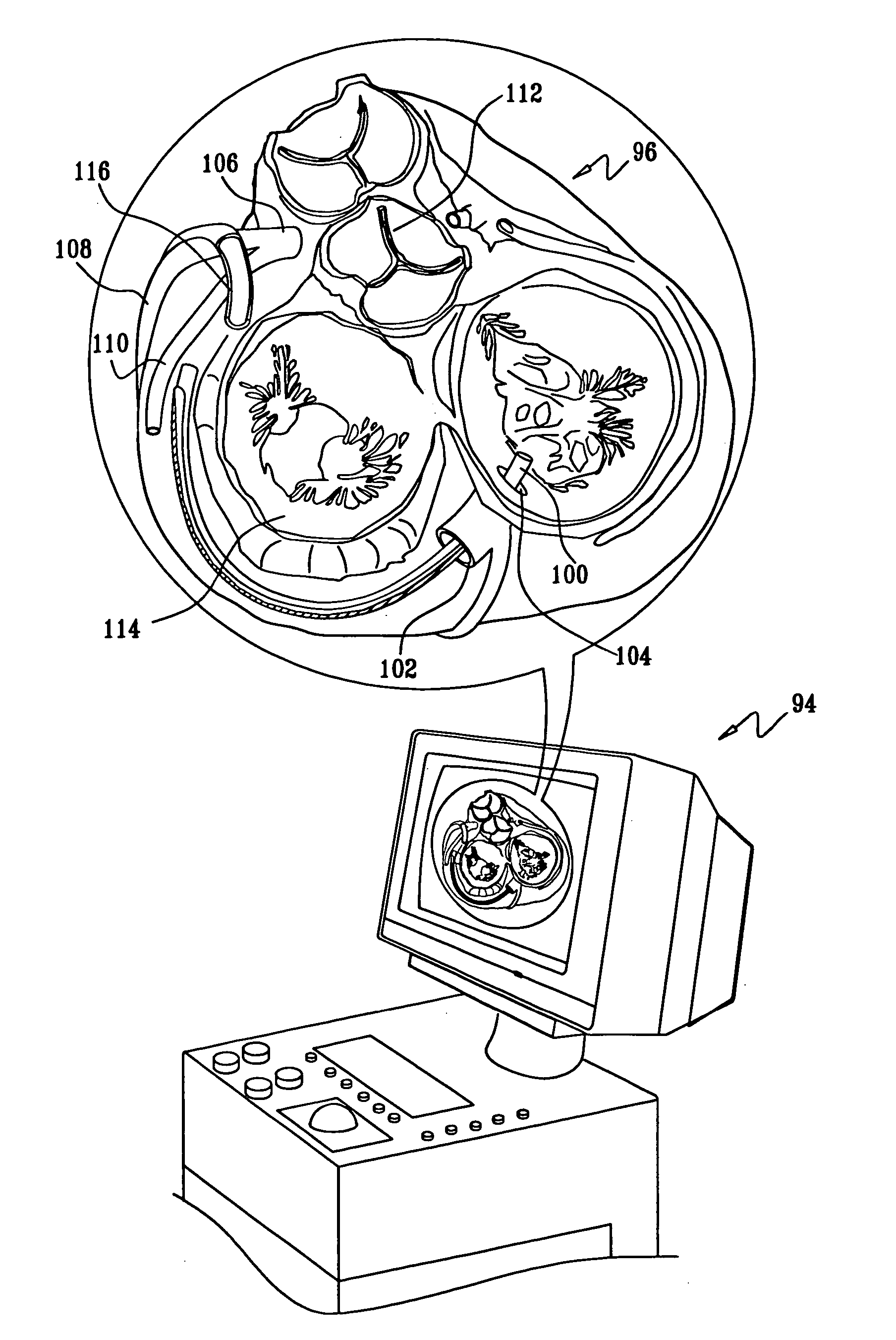
[0078] Reference is now made to FIG. 6, which is a screen display 94 illustrating a cut-away processed view of the superior aspect of a heart 96 in registration with an image of an annuloplasty device 98 that would be deployed using a catheter 100 in accordance with a disclosed embodiment of the invention. The great vessels and upper portions of the atria are removed. The image of the heart may be pre-acquired using one of the anatomic imaging techniques and the location positioning system described above, then processed and enhanced by an image processor. Alternatively, the image of the heart may be acquired during deployment of the catheter 100 using the catheter 28 as shown in FIG. 1. The images of the annuloplasty device 98 and catheter 100 are constructed intraoperatively, for example using the system 20 (FIG. 1). Features of the heart 96 that are visible on FIG. 6 include its coronary sinus 102 and ostium 104, left main coronary artery 106, anterior descending branch 108, left...


PUM


Abstract

During a minimally invasive deployment of a mitral valvuloplasty device into the coronary sinus near realtime tracking of the device is monitored to determine whether the device is compressing the left circumflex coronary artery or is likely to do so. In one embodiment of the invention, one or more position sensors are included in the catheter that is used to deploy the constricting implant and or in the implant itself. The position of the device is determined during deployment, and compared to the location of the left circumflex coronary artery, which may be determined by mapping relative to a pre-acquired image or by simultaneous intracardiac ultrasound imaging.

Description

BACKGROUND OF THE INVENTION [0001] 1. Field of the Invention [0002] This invention relates to methods and systems for the treatment of valvular disease of the heart. More particularly, this invention relates to monitoring of percutaneous mitral valvuloplasty procedures. [0003] 2. Description of the Related Art [0004] A number of different treatments are known or in development to effect minimally invasive mitral valvuloplasty, in order to treat conditions such as mitral regurgitation. One family of solutions takes advantage of the fact that the coronary sinus partially encircles the mitral valve along the atrioventricular groove, generally in the same plane as the mitral valve annulus. A number of companies have developed implants that may be inserted into the coronary sinus and then actuated, typically by mechanical or thermal means to cinch or otherwise constrict the mitral valve annulus. This tends to reduce the radius of curvature of the annulus, which results in improved coapta...

Claims


Application Information

Patent Timeline
Patent Type & Authority Applications(United States)
IPC IPC(8): A61B8/14A61F2/24A61B8/06
CPCA61B5/06A61B8/445A61B6/541A61B8/12A61B8/4488A61B8/543A61B19/52A61B19/5244A61B2017/00243A61B2019/505A61B2019/5251A61B2019/5263A61B2019/5276A61B2019/528A61B5/7285A61B90/36A61B2034/2063A61B34/20A61B2090/3784A61B2034/105A61B2034/2051A61B2090/378
Inventor SCHWARTZ, YITZHACK
Owner BIOSENSE WEBSTER INC
Why Eureka
Try Eureka