

Exhaust gas-purifying device
a technology of exhaust gas and purification device, which is applied in the direction of machine/engine, magnetic separation, separation process, etc., can solve the problems of clogging of particulate filter, excessive amount of particles, etc., and achieve the effect of reliable burning o
- Summary
- Abstract
- Description
- Claims
- Application Information
AI Technical Summary
Benefits of technology
Problems solved by technology
Method used
Image

Examples
Embodiment Construction
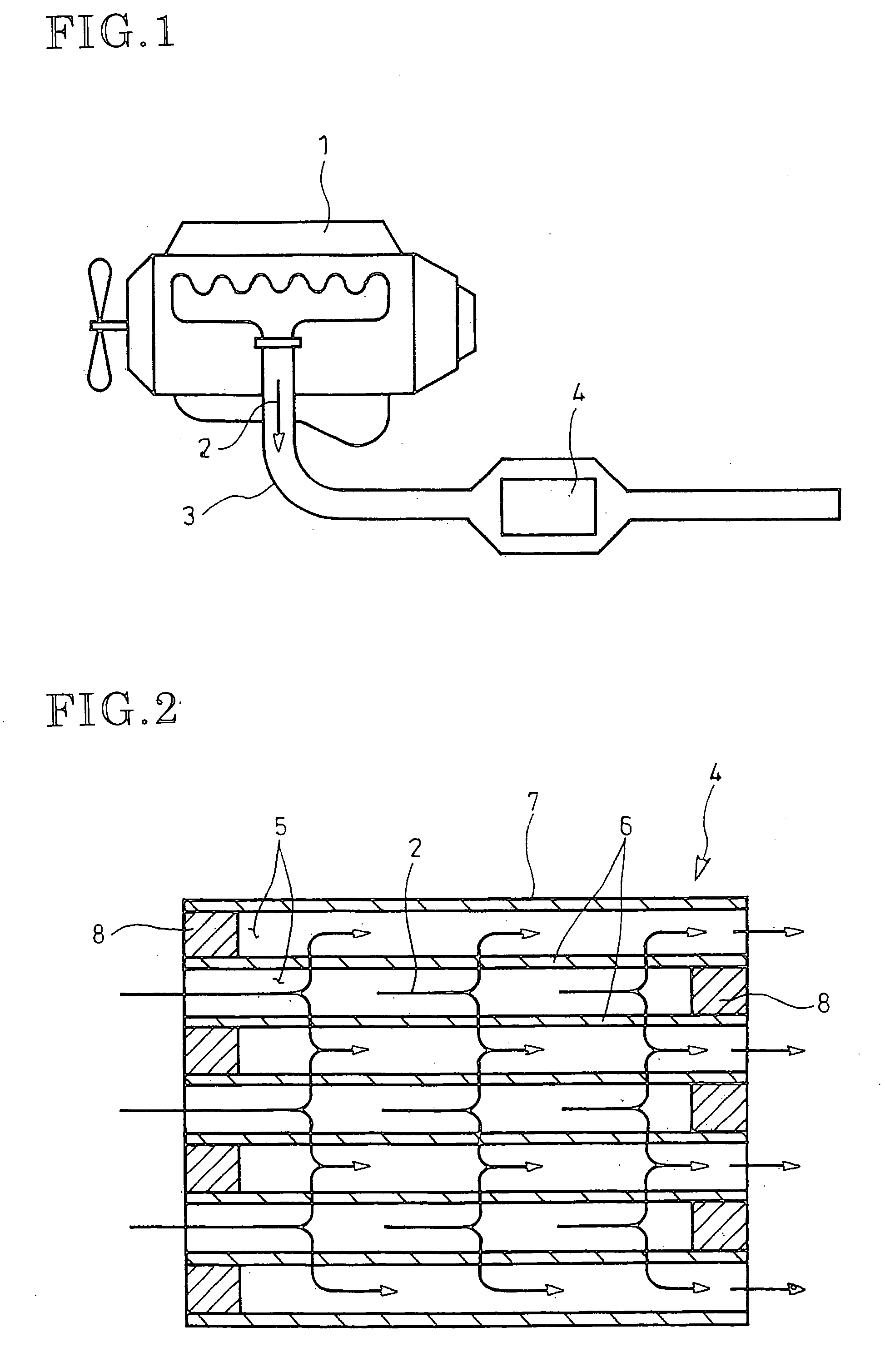
[0043] An embodiment of the invention will be described in conjunction with the drawings.
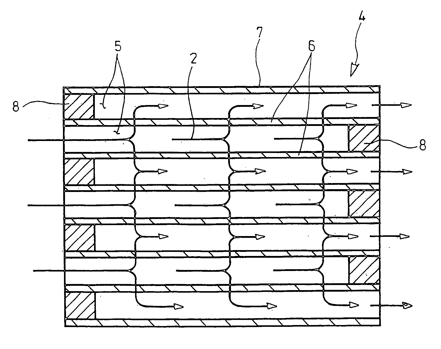
[0044]FIGS. 3 and 4 show an embodiment of the invention in which parts similar to those in FIGS. 1 and 2 are represented by the same reference numerals.
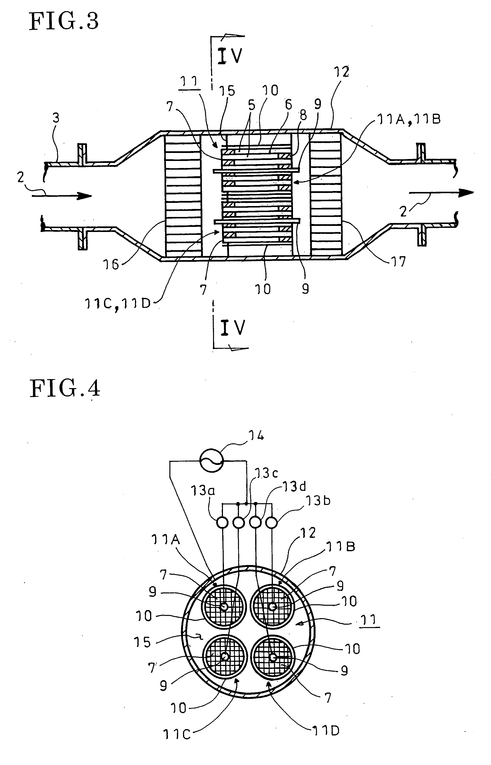
[0045] As shown in FIGS. 3 and 4, used in an exhaust emission control device of the invention is a plasma regenerative particulate filter 11 comprising a filter body 7 similar to that shown in FIG. 2 above and rod-like and cylindrical electrodes 9 and 10 so as to generate plasma in the filter body 7. Shown is an example of the plasma regenerative particulate filter 11 divided into a plurality of (four in the figure shown) smaller units 11A, 11B, 11C and 11D which are arranged in parallel with each other within the filter casing 12.
[0046] The filter body 7 in each of the smaller units 11A, 11B, 11C and 11D has the rod-like electrode 9 inserted into an axis of the filter body 7 and the cylindrical electrode 10 fitted over the outer periphery of ...
PUM
| Property | Measurement | Unit |
|---|---|---|
| Power | aaaaa | aaaaa |
| Electric potential / voltage | aaaaa | aaaaa |
| Heat | aaaaa | aaaaa |
Abstract
Description
Claims
Application Information