

Method of using sulfur fluoride for removing surface deposits
a sulfur fluoride and surface deposit technology, applied in the direction of chemistry apparatus and processes, cleaning of hollow articles, coatings, etc., can solve the problems of inability to clean chamber parts directly exposed to plasma, inability to clean plasma in the sitting room, and expensive and time-consuming parts replacemen
- Summary
- Abstract
- Description
- Claims
- Application Information
AI Technical Summary
Problems solved by technology
Method used
Image

Examples
example 1
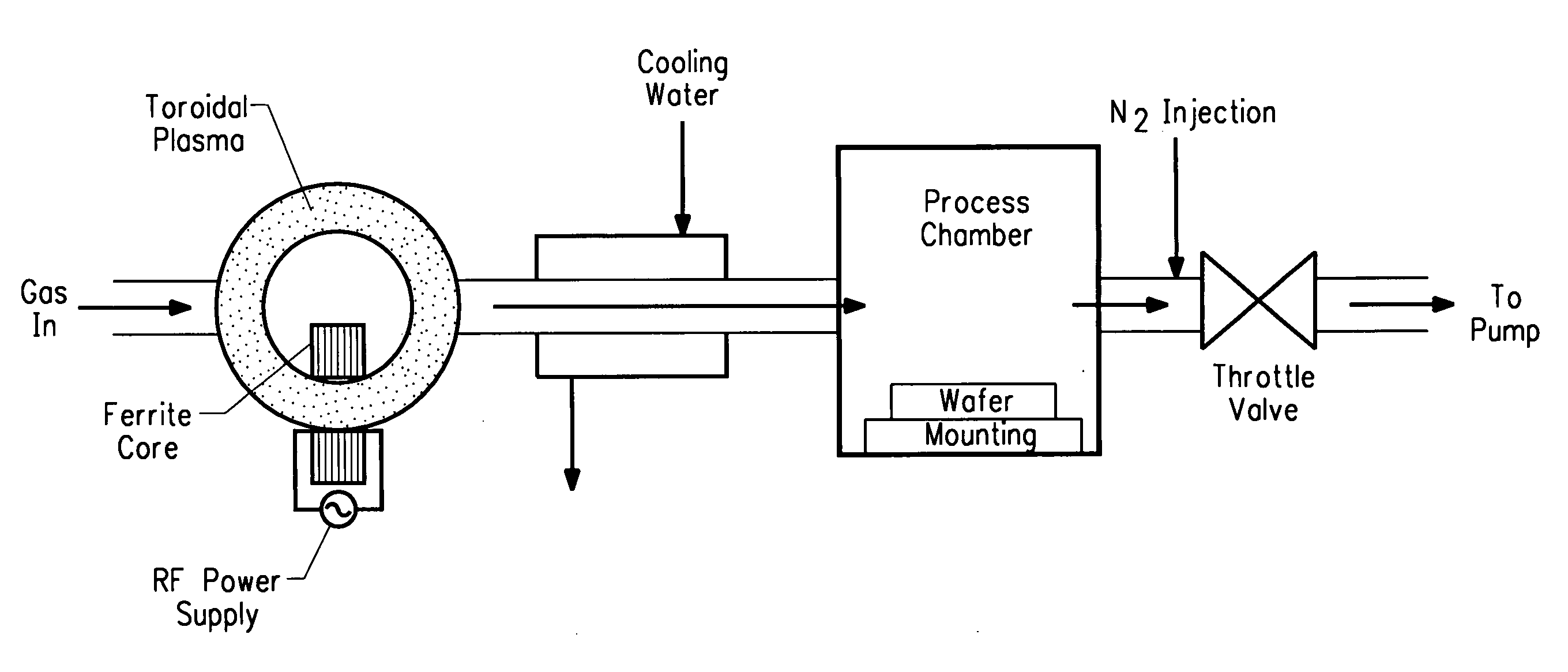
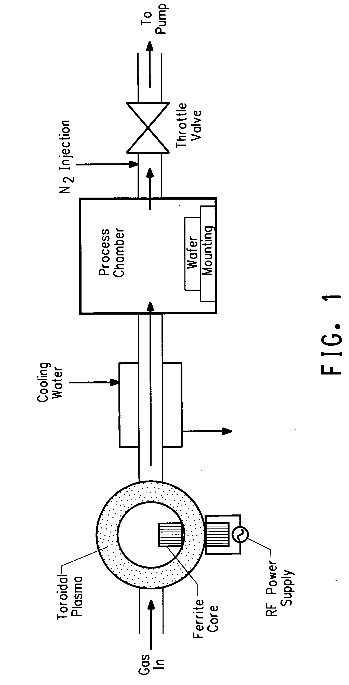
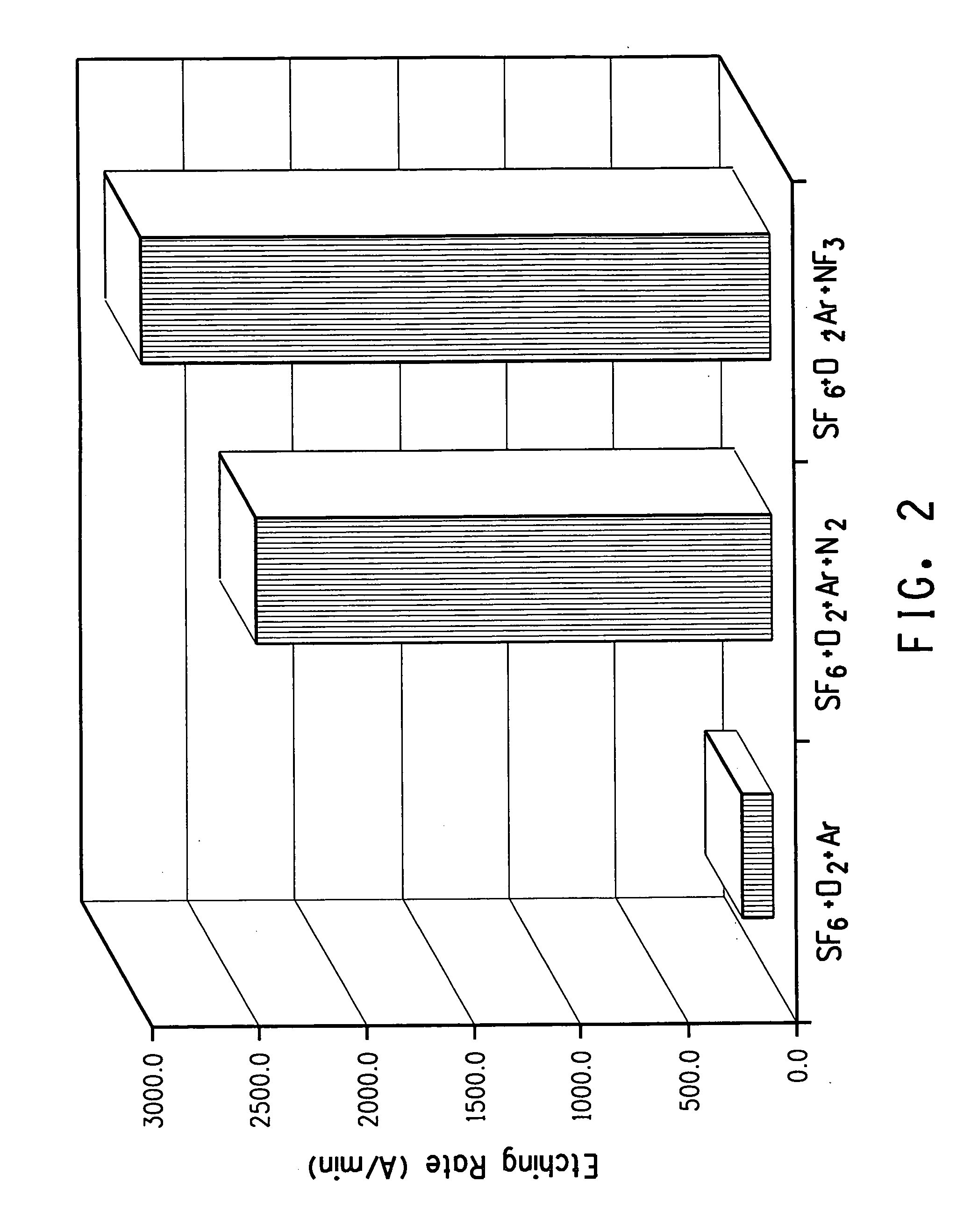
[0028] This Example demonstrated the effect of nitrogen source addition on the silicon nitride etching rate of SF6 / O2 / Ar systems. The results are also shown in FIG. 2. In this experiment, the feeding gas composed of O2, SF6, Ar and optionally N2 or NF3 wherein O2 flow rate was 667 sccm, Ar flow rate was 2000 sccm, SF6 flow rate was 667 sccm. Chamber pressure was 2 torr. The feeding gas was activated by the 400 KHz 4.8 Kw RF power to a neutral temperature more than 3000 K. The activated gas then entered the process chamber and etched the silicon nitride surface deposits on the mounting with the temperature controlled at 50° C. When there was no nitrogen source in the feeding gas mixture, i.e. the feeding gas mixture was composed of 667 sccm O2, 2000 sccm Ar and 667 sccm SF6, the etching rate was only 189 Å / min. As shown in middle column of FIG. 2, when 100 sccm N2 was added in the feeding gas mixture, i.e. the feeding gas mixture was composed of 100 sccm N2, 667 sccm O2, 2000 sccm Ar...
example 3
[0030] This Example demonstrated the effect of nitrogen source addition on the SiO2 etching rate of SF6 / O2 / Ar systems. The results are also shown in FIG. 4. In this experiment, the feeding gas composed of O2, SF6, Ar and optionally N2 wherein O2 flow rate was 667 sccm, Ar flow rate was 2000 sccm, SF6 flow rate was 667 sccm. Chamber pressure was 2 torr. The feeding gas was activated by the 400 KHz 4.8 Kw RF power to a neutral temperature more than 3000 K. The activated gas then entered the process chamber and etched the SiO2 surface deposits on the mounting with the temperature controlled at 100° C. When there was no nitrogen source in the feeding gas mixture, i.e. the feeding gas mixture was composed of 667 sccm O2, 2000 sccm Ar and 667 sccm SF6, the etching rate was only 736 Å / min. When 100 sccm N2 was added in the feeding gas mixture, i.e. the feeding gas mixture was composed of 100 sccm N2, 667 sccm O2, 2000 sccm Ar and 667 sccm SF6, the etching rate of SiO2 was increased from 73...
example 4
[0031] In this experiment, the feeding gas composed of O2, N2, SF6 and Ar, wherein O2 flow rate was 667 sccm, N2 flow was 100 sccm, Ar flow rate was 2000 sccm, SF6 flow rate was 667 sccm. Chamber pressure was 2 torr. The feeding gas mixture was activated by the 400 KHz 4.8 Kw RF power to a neutral temperature more than 3000 K. The activated gas then entered the process chamber and treated for 10 minutes a Sapphire wafer surface on the mounting with the temperature controlled at 25° C. FIG. 5 demonstrates that the surface was clean from sulfur after treatment.
PUM
| Property | Measurement | Unit |
|---|---|---|
| Temperature | aaaaa | aaaaa |
| Pressure | aaaaa | aaaaa |
| Pressure | aaaaa | aaaaa |
Abstract
Description
Claims
Application Information