Well Servicing Rig and Manifold Assembly

a technology for servicing rigs and manifolds, which is applied in the direction of drilling machines and methods, drilling accessories, fluid removal, etc., can solve the problems of high labor intensity, large work area footprint created by such set-ups, and high labor intensity

Inactive Publication Date: 2007-02-08
FRAC SOURCE
View PDF2 Cites 192 Cited by
  • Summary
  • Abstract
  • Description
  • Claims
  • Application Information

AI Technical Summary

Problems solved by technology

The assembly and subsequent disassembly and transport of so many units to another wellsite upon completion of an operation is time consuming and highly labour intensive, and hence costly.
One particularly costly and time-consuming component of such set-up for a fracing operation is the erection of the piping array (also often referred to as a “manifold assembly”).
The large work area footprint created by such set-up is undesireable and potentially dangerous should a worker trip on such piping.

Method used


Image

  • Well Servicing Rig and Manifold Assembly
  • Well Servicing Rig and Manifold Assembly
  • Well Servicing Rig and Manifold Assembly

Examples


Embodiment Construction

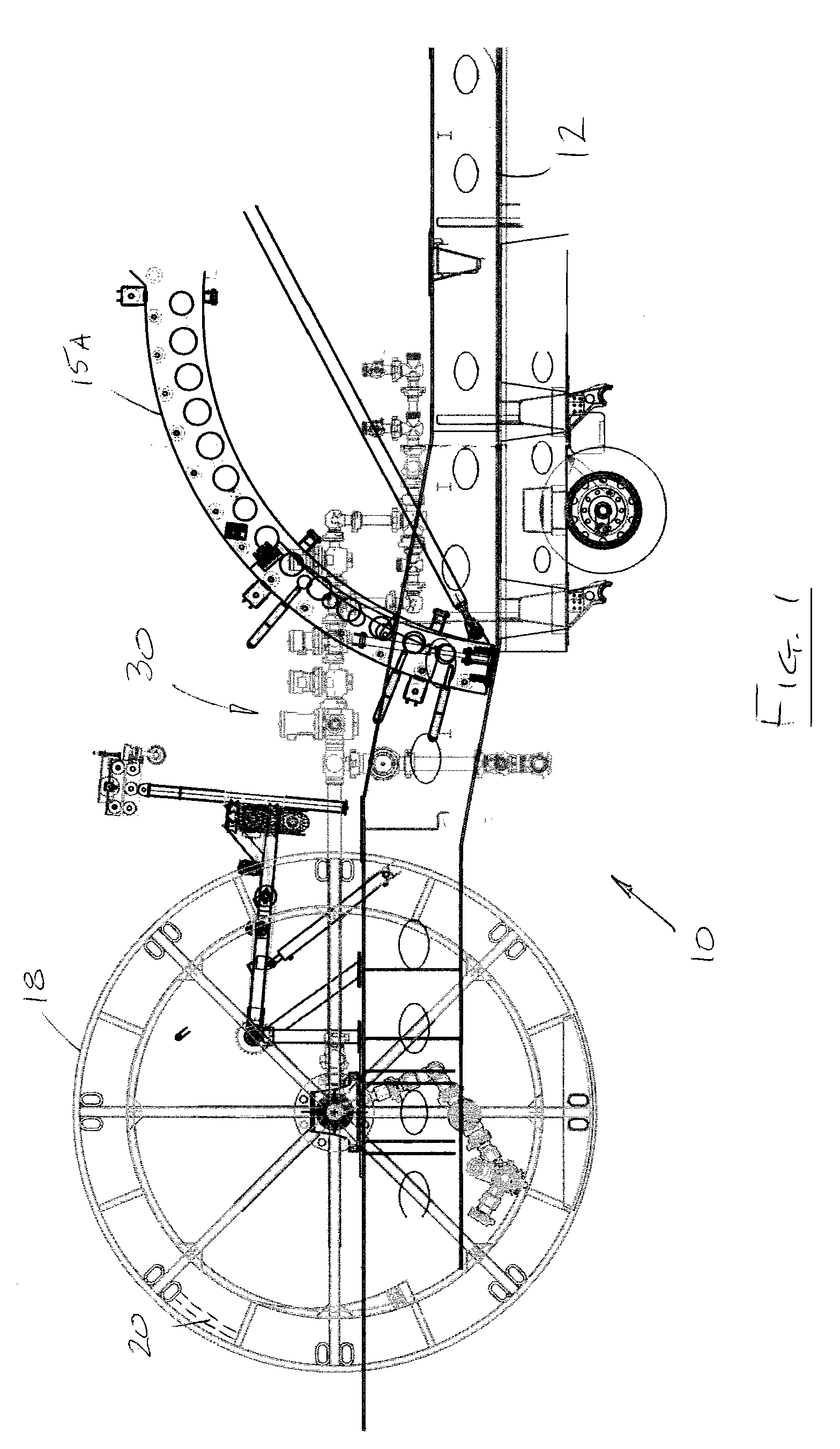
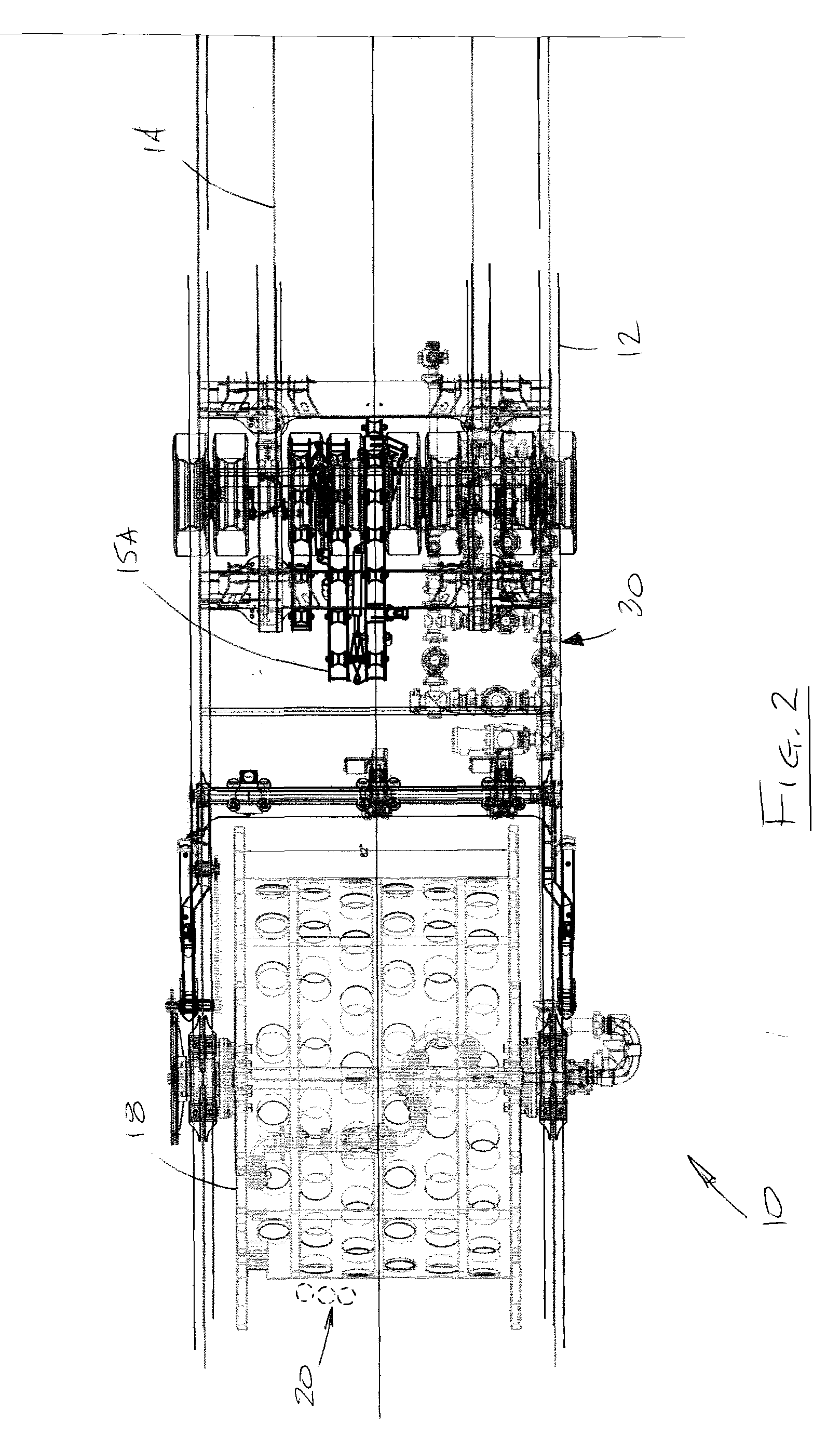
[0032] Reference is first made to FIGS. 1 to 3c which show a servicing unit for an underground formation which in the preferred embodiment is in the form of a coiled tubing unit, or rig, generally indicated by the reference numeral 10. The present rig can service various types of hydrocarbon bearing formations, including coal formations (or beds). It is suited for typical coiled tubing functions, such as conventional stimulation operations relating to coiled tubing, as well as for fracturing (“fracing”) operations of coal beds to enhance production of coal bed methane.

[0033] Some of the basic components of the rig are a base, a mast pivotally mounted relative to the base, and servicing equipment for a well, or wellbore, leading to the underground formation. “Servicing” is defined herein as typical functions related to coiled tubing, including stimulation and fracing operations. The base is a mobile carrier in the form of a wheeled trailer 12 adapted to be pulled by a motorized vehi...


PUM


Abstract

A well servicing rig for communicating with a fluid source and an effluent reservoir (such as a flow back tank) has an apparatus for holding and dispensing coiled tubing. A manifold assembly is advantageously located on the rig for routing the pressurized fluid (such as nitrogen gas mixed with proppant) from the fluid source between the coiled tubing apparatus, the well and the effluent reservoir. The manifold assembly controls the flow of the fluid to perform fracturing operations, for reverse fluid circulation, for a common coiled tubing operation, for pressure testing, and the like. The assembly includes remotely controlled valves and pressure transducers for controlling the fluid flow, and chokes for diffusing fluid energy prior to entering the effluent reservoir. The rig, fluid source, effluent reservoir and a fluid pumper provide a novel method of servicing an underground formation (such as a coal bed) for natural gas.

Description

FIELD OF THE INVENTION [0001] The present invention relates generally to well servicing units, and in particular relates to a novel coiled tubing rig having a novel manifold assembly for routing and controlling fluid flow between a fluid source and an underground formation, such as a coal bed. BACKGROUND OF THE INVENTION [0002] A large assortment of various rigs and vehicles are currently required to service (namely to drill, fracture and the like) both conventional and coal bed methane wells for hydrocarbon production, such as natural gas. A term of art for “natural gas from coal” is “NGC”. Conventional fracturing (“fracing”) and stimulation of NGC formations currently requires about 13 or more vehicles / rigs for such an operation, including at least one trailer to transport numerous components of a conventional piping array to the NGC wellsite. The assembly and subsequent disassembly and transport of so many units to another wellsite upon completion of an operation is time consumin...

Claims


Application Information

Patent Timeline
Patent Type & Authority Applications(United States)
IPC IPC(8): E21B43/26
CPCE21B7/02
Inventor ANDREYCHUK, MARKSTROMQUIST, MARTY
Owner FRAC SOURCE
Why Eureka
Try Eureka