Supercharge Your Innovation With Domain-Expert AI Agents!

Eyeground observation device and eyeground observation method

a technology of eyeground observation and eyeground, which is applied in the field of retina observation apparatuses and retina observation methods, can solve the problems of affecting so as to improve the picture quality, and improve the quality of the retina image

Inactive Publication Date: 2007-02-08
KK TOPCON
View PDF1 Cites 15 Cited by
  • Summary
  • Abstract
  • Description
  • Claims
  • Application Information

AI Technical Summary

Benefits of technology

[0005] The present invention addresses the problems described above, with an object of adjusting the correction to be made by the compensating optical device so that the quality of the retina image is improved and obtaining an appropriate amount of correction. Another object of the present invention is to obtain an appropriate amount of correction for improving the picture quality in accordance with a value obtained from pattern matching between the manner in which a visual target is perceived by an eye under examination and a certain pattern template, or an MTF (modulation transfer function). A further object of the present invention is to provide an retina image corrected by an appropriate correction amount. A still another object of the present invention is to improve the quality of the retina image by means of a voltage-change template provided to adjust the correction amount of the compensating optical device. A still further object of the present invention is to evaluate the image quality in consideration of the size of the retina cell and to enable observations up to the cell level.

Problems solved by technology

The compensating optical device (such as the deformable mirror) would not correct the aberration completely and would sometimes leave a great aberration.
A remaining aberration of that level has made it difficult to improve the picture quality of the retina image.
Even if the deformation of the compensating optical device brings the RMS of error to the level of the asymptotic value, the remaining aberration may hinder an optimum image from being obtained.

Method used


Image

  • Eyeground observation device and eyeground observation method
  • Eyeground observation device and eyeground observation method
  • Eyeground observation device and eyeground observation method

Examples


Embodiment Construction

1. Hardware Configuration

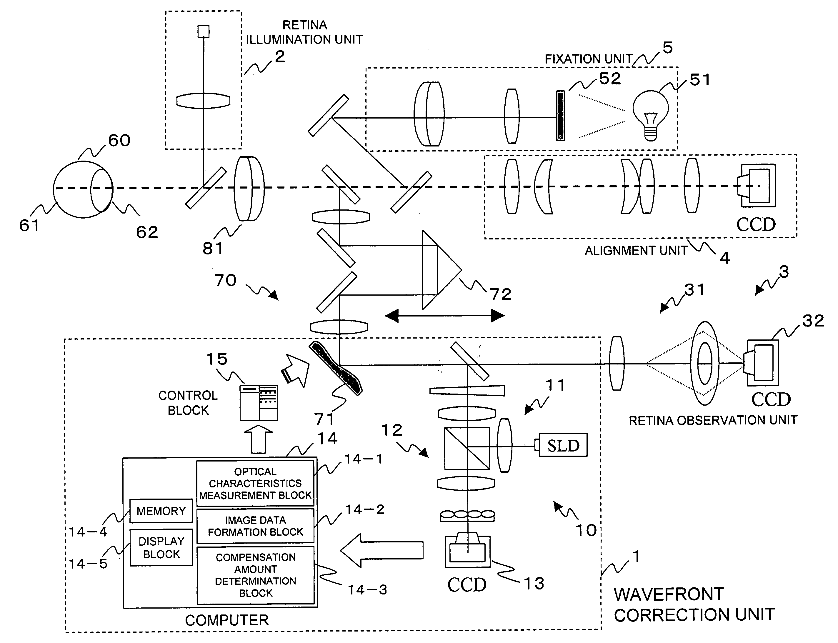
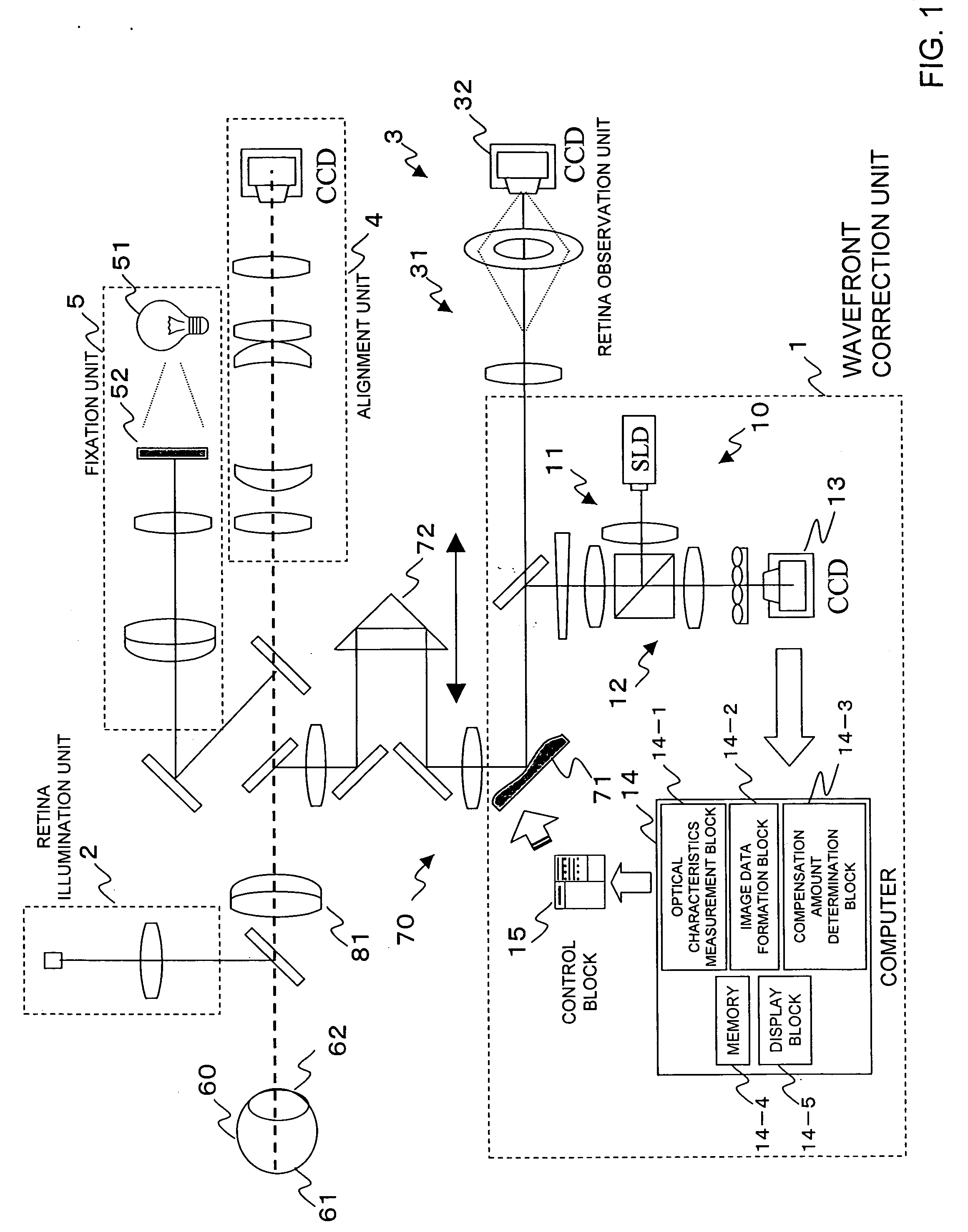
[0047]FIG. 1 is a diagram showing the configuration of an retina observation apparatus. The retina observation apparatus includes a wavefront correction unit 1, an retina illumination unit 2, an retina observation unit 3, an alignment unit 4, a fixation unit 5, and a compensating optical section 70. The wavefront correction unit 1 includes a point-image-projecting optical block 11, a point-image-light-receiving optical block 12, a wavefront measurement block 10 containing a point-image-light-receiving section 13, a computer 14, and a control block 15. The retina observation unit 3 includes an retina-image-forming optical block 31 and an retina-image-light-receiving section 32. The computer 14 includes an optical characteristics measurement block 14-1, an image data formation block 14-2, a compensation amount determination block 14-3, and a memory 14-4. The computer 14 may also include a display block 14-5, an input block, and the like. The figure shows the...


PUM


Abstract

It is possible to improve the quality of an image of an eyeground, thereby acquiring an optimal image. An eyeground observation system (3) acquires an eyeground image via a compensation optical section (70) correcting the image of the eyeground obtained by illumination of an eyeground illumination system (2). A wave front correction system (1) measures wave front measurement data including a wave front aberration of the eye to be checked and / or aberration to be corrected, thereby acquiring the optical characteristic of the eye to be checked. An image data formation section (14-2) performs simulation of viewing at the eyeground, thereby calculating the simulation image data or MTF data. A correction amount decision section (14-3) decides a correction amount according to a voltage change template stored in a memory (144) and outputs it to a control section (15). Moreover, the correction amount decision section (14-3) uses the simulation result for a plurality of voltage change templates so as to calculate a value indicating the matching degree of the pattern or MTF data corresponding to a spatial frequency of cells of the eyeground and decide an appropriate correction amount

Description

TECHNICAL FIELD [0001] The present invention relates to retina observation apparatuses and retina observation methods, and more specifically, to an retina observation apparatus and an retina observation method that allow the aberration of an eye under examination to be corrected by means of a compensating optical device and allow observations to be made up to the cell level. BACKGROUND ART [0002] In the conventional retina observation, the retina of an eye under examination has been observed with the aberration of the eye minimized. There have been disclosed a method and an apparatus of improving the eyesight and the resolution of an image on the retina by deforming an optical correcting member like a deformable mirror (see, for example, patent document 1). In the apparatus, a Hartmann-Shack wavefront sensor determines the wavefront aberration value of the eye, and the deformable mirror is deformed to correct the aberration value accordingly. The process of deforming the deformable ...

Claims


Application Information

Patent Timeline
Patent Type & Authority Applications(United States)
IPC IPC(8): A61B3/14A61B3/12
CPCA61B3/1015G02B26/06G02B21/0004A61B3/145
Inventor YAMAGUCHI, TATSUOMIHASHI, TOSHIFUMI
Owner KK TOPCON
Features
  • R&D
  • Intellectual Property
  • Life Sciences
  • Materials
  • Tech Scout
  • Unparalleled Data Quality
  • Higher Quality Content
  • 60% Fewer Hallucinations
Learn More