Variable refractive surface

a refractive surface and variable technology, applied in the field of variable refractive surface elements, can solve the problems of deterioration of the readout signal, deterioration of the optical recording system readout signal, and reducing the performance of the optical system, so as to achieve the effect of cheap manufacturing

Inactive Publication Date: 2007-02-08
KONINKLIJKE PHILIPS ELECTRONICS NV
View PDF3 Cites 3 Cited by
  • Summary
  • Abstract
  • Description
  • Claims
  • Application Information

AI Technical Summary

Benefits of technology

[0014] In such an element, the shape of the meniscus may be altered by both electrodes. The meniscus effectively provides a refractive surface, the shape of which is variable. Use of the electrode extending through the meniscus allows the meniscus to be formed into a number of novel shapes, including shapes suitable for correcting spherical aberration. Such an element is relatively cheap to manufacture compared to a liquid crystal cell.

Problems solved by technology

In various optical systems, aberrations can arise which are unwanted, and which tend to decrease the performance of the optical system.
Warped optical discs result in coma aberration in the scanning beam, thus deteriorating the readout signal of the optical recording system.
Further, the system may be effected by temperature changes e.g. the objective lens in optical recording systems can give rise to spherical aberration when its temperature is elevated, thus leading to deterioration of the readout signal.
When switching from scanning one information layer to another information layer (e.g. from the first to the second layer in a dual layer disc), spherical aberration arises due to the different covering layer thicknesses that have to be traversed by the scanning beam.
One disadvantage of such a liquid crystal device is that it requires a relatively expensive liquid crystal cell.

Method used


Image

  • Variable refractive surface
  • Variable refractive surface
  • Variable refractive surface

Examples


Embodiment Construction

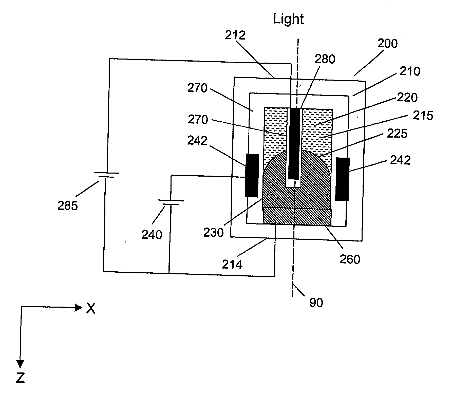
[0024] The present inventors have realised that an electrowetting device having a meniscus between two fluids of different refractive indices can be used be provide aberration compensation.

[0025] Electrowetting devices are devices that utilise the electrowetting phenomenon to operate. In electrowetting, the three-phase contact angle is changed with applied voltage. The three-phases constitute two fluids and a solid. Typically, at least one of the fluids is a liquid.

[0026] A fluid is a substance that alters it shape in response to any force, that tends to flow or to conform to the outline of its chamber, and that includes gases, vapours, liquids and mixtures of solids and liquids capable of flow.

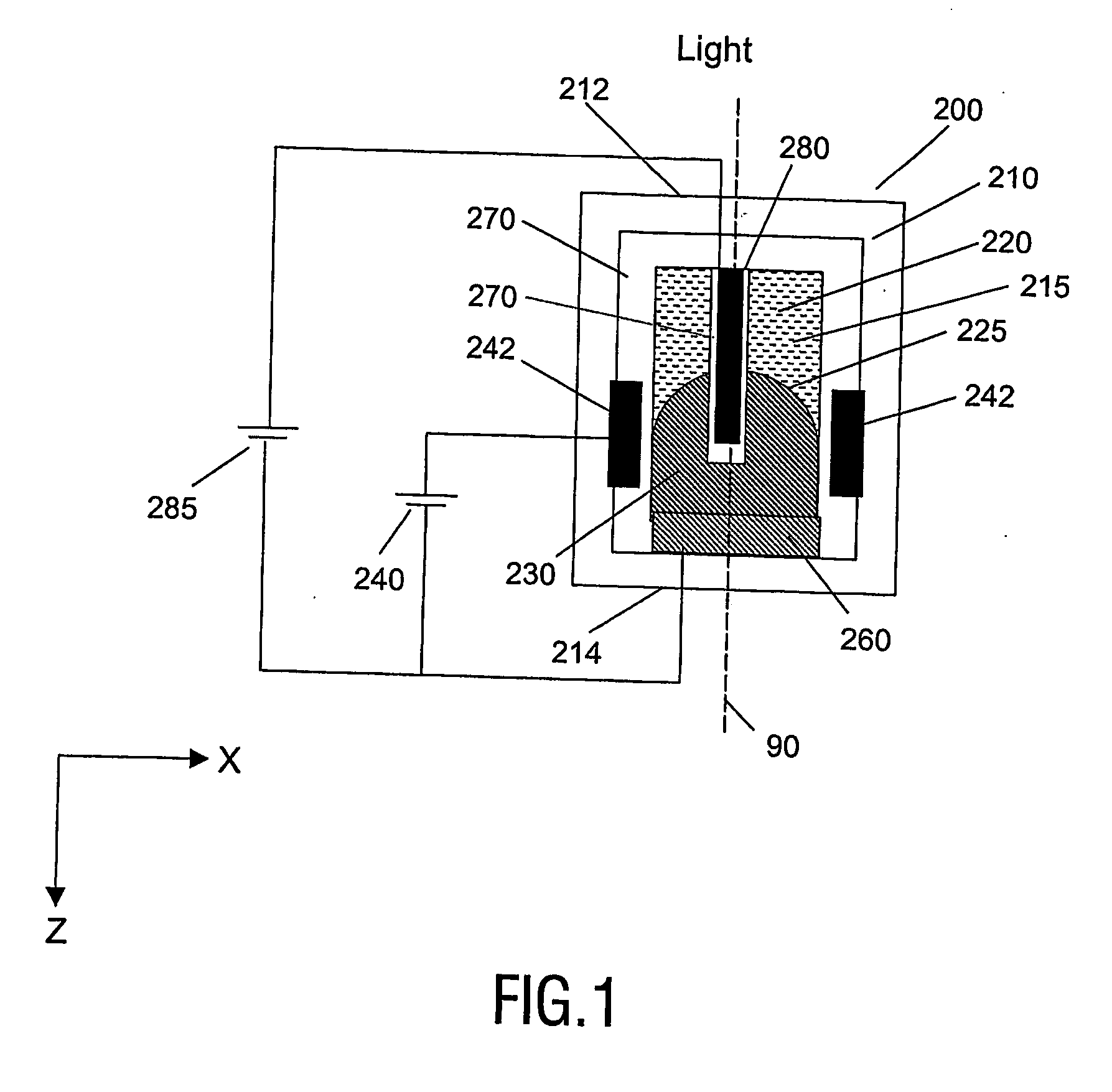
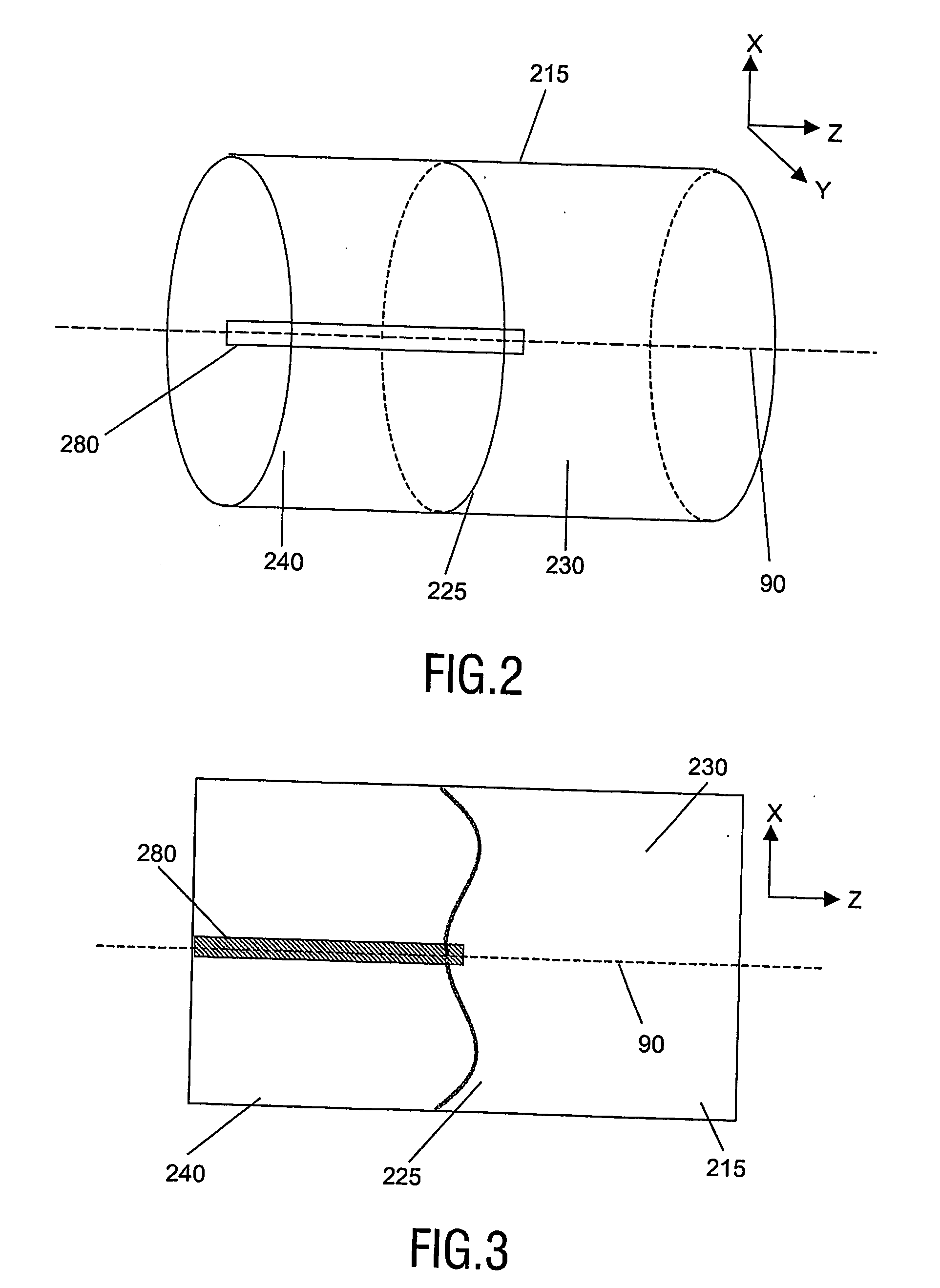
[0027]FIG. 1 illustrates an element 200 in accordance with an embodiment of the present invention. The element 200 is an optical element (i.e. it is arranged to alter the properties of light incident upon the device), and in this instance the element 200 is arranged to provide a variable r...


PUM

PropertyMeasurementUnit
refractive surfaceaaaaaaaaaa
indices of refractionaaaaaaaaaa
meniscus perimeteraaaaaaaaaa

Abstract

An optical element (200; 300) for providing a variable refractive surface. The element comprises a chamber (215) defined by at least one side wall (270), with an optical axis (90) extending through the chamber (215). The chamber (215) contains a first fluid (220) and a second fluid (230) in contact over a meniscus (225) extending transverse the optical axis (90). The perimeter of the meniscus (225) is constrained by said side wall (270). The fluids (220, 230) are substantially immiscible and have different indices of refraction. A first electrowetting electrode (242; 243) is arranged to act on at least a portion of the meniscus perimeter constrained by said side wall (270). A second electrowetting electrode (280) extends through the meniscus (225).

Description

FIELD OF THE INVENTION [0001] The present invention relates to an element providing a variable refractive surface, to devices including such elements, and to methods of manufacture of such elements and such devices. Such an element is particularly suitable for, but not limited to, correcting spherical aberrations within optical scanning devices. BACKGROUND OF THE INVENTION [0002] In various optical systems, aberrations can arise which are unwanted, and which tend to decrease the performance of the optical system. [0003] For instance, optical discs such as CD (Compact Disc), DVD (Digital Video Disc or Digital Versatile Disc), and BD (Blu-ray Disc) are known as information recording media on which information is optically recorded or reproduced. Warped optical discs result in coma aberration in the scanning beam, thus deteriorating the readout signal of the optical recording system. Further, the system may be effected by temperature changes e.g. the objective lens in optical recording...

Claims


Application Information

Patent Timeline
Patent Type & Authority Applications(United States)
IPC IPC(8): G02F1/03G02B3/14G02B26/02G02B27/00G11B7/00G11B7/135
CPCG02B3/14G02B26/005G02B27/005G11B2007/13727G11B7/1374G11B2007/0006G02B27/0068G02B3/12
Inventor HENDRIKS, BERNARDUS HENDRIKUSKUIPER, STEIN
Owner KONINKLIJKE PHILIPS ELECTRONICS NV
Why Eureka
Try Eureka