
Molded product and manufacturing method thereof

a technology of molded products and manufacturing methods, applied in the direction of solid balls, transportation and packaging, sports equipment, etc., can solve the problems of difficulty in forming an insulating layer not defective between metal bodies, and problems such as problems

Inactive Publication Date: 2007-02-08
HITACHI CABLE
View PDF5 Cites 13 Cited by
  • Summary
  • Abstract
  • Description
  • Claims
  • Application Information

AI Technical Summary

Benefits of technology

[0012] Although surroundings of metal plates 101, 102 or clearance 105 between them becomes a part on which the electric field concentrates when the voltage is applied to metal bodies 101, 102, the insulation performance decreases when flaking off is caused on the interfaces of metal bodies 101, 102 and the insulating material by the heating and cooling repeated by the change of the turn-on environment (or, system requirements) or by “shrinkage” when the insulating material is molded, and the possibility that the dielectric breakdown is caused rises. A partial electric discharge may occur on the interface of metal bodies 101, 102 and the insulating material, and lifetime may be remarkably decreased. Therefore, it is necessary to bond insulating material and metal bodies 101, 102 strongly, and mold release characteristics deteriorate when the insulating material contains the adhesive. In addition, the viscosity of molten resin 116 rises, and the formability deteriorates. Further, there is a possibility that the adhesive flows by the injection pressure of the insulating material when the adhesive is spread on metal bodies 101, 102 beforehand, and the bonding power varies.
[0016] Optionally, the bonding layer composed of the adhesive that melting point T3 is in the relation of T3<T1 is provided between said metal plates and said spacer polymer, and between said metal plates and said molded part. Preferably, the first and second bonding layers composed of the adhesive that melting point T3 is in the relation of T3<T1 are provided between said metal plates and said spacer polymer, and between said metal plates and said molded part, respectively, and each adhesive which composes said first and second bonding layers has high compatibility.
[0022] Plural metal plates can be coated with insulating polymer according to the present invention. Moreover, it is possible to insulate between plural metal plates by a thin and uniform insulating layer.

Problems solved by technology

There are three main problems when the insulative molded product described above is molded by injection molding.
Therefore, it is difficult to form an insulating layer not defective between metal bodies 101,102.
Therefore, problem may occur in such a case.

Method used


Image

  • Molded product and manufacturing method thereof
  • Molded product and manufacturing method thereof
  • Molded product and manufacturing method thereof

Examples


embodiment 1

(Embodiment 1)

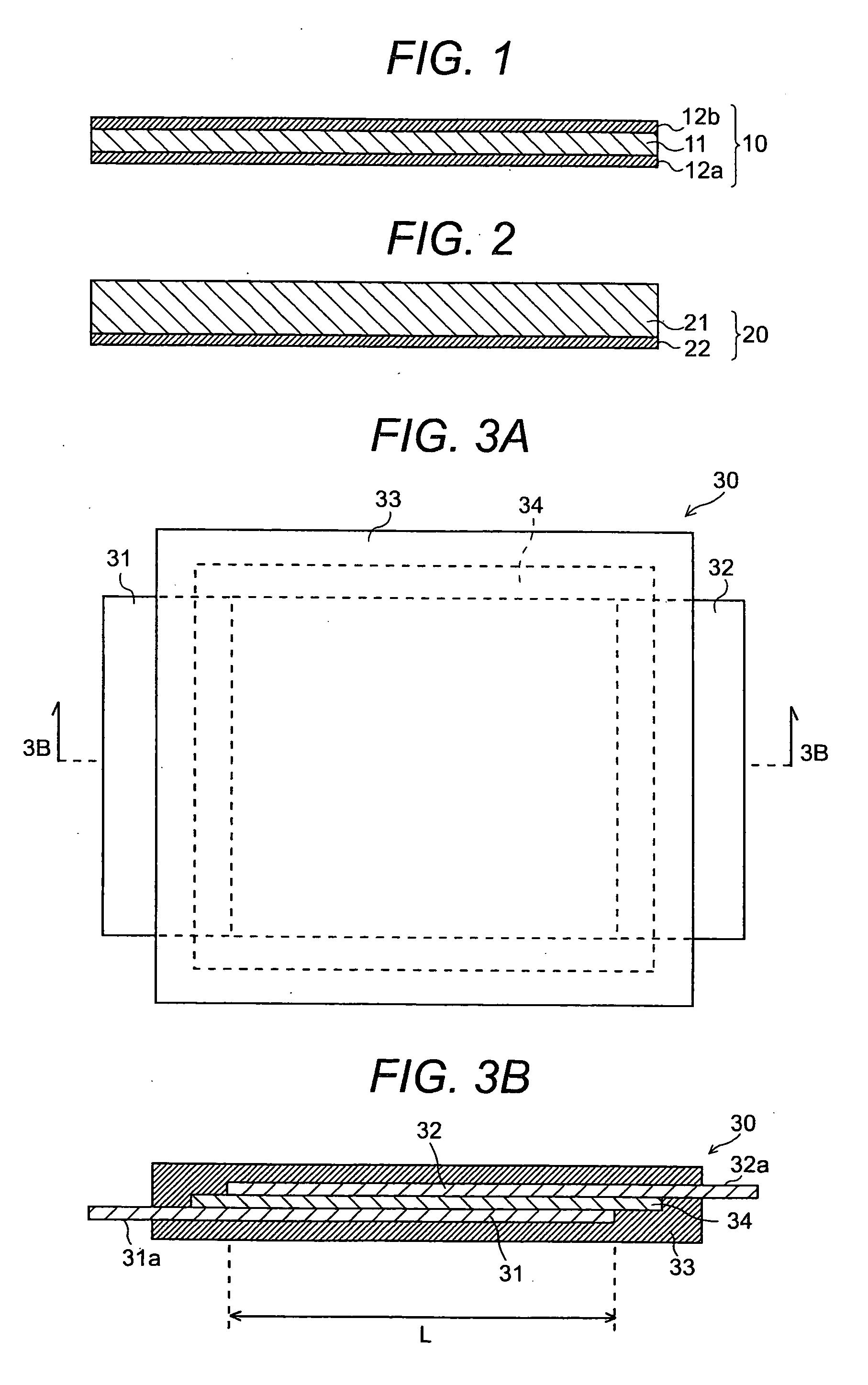
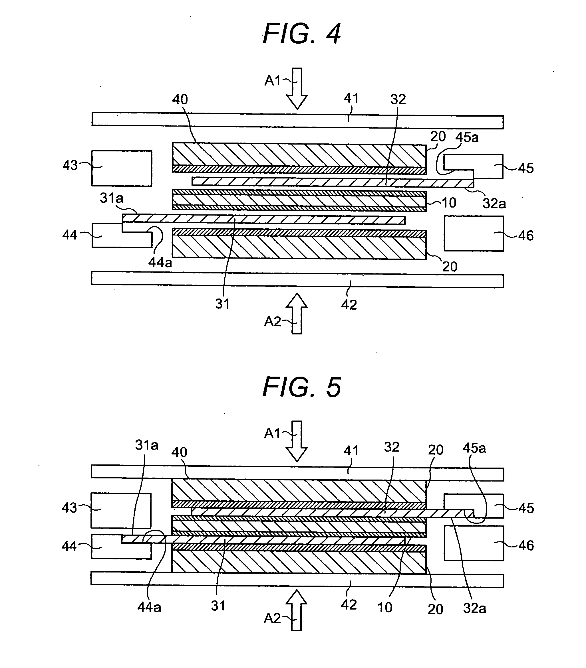
[0066] PPE sheet (Asahi Kasei Corporation, Zairon 540Z, and thickness t is 0.4 mm) where the heat-hardening bonding layer had been spread on both sides as shown in FIG. 1 was prepared. The sheet was cut into the size (220 mm×230 mm) whose length and breadth is 10 mm larger than the lap area of two sheet coppers. Moreover, flame-resistant PE resin sheet (UBE INDUSTRIES, LTD. Z555, and thickness t is 2.5 mm) which the hot melt adhesive layer was spread on one side as shown in FIG. 2 was prepared. The flame-resistant PE resin sheet was cut (220 mm×230 mm×2.5 mm) so that the volume of two flame -resistant PE resin sheet may become more than the value obtained by subtracting the volume of the sheet copper and the PPE sheet from the volume of the molded product of 240 mm×250 mm×5 km. Further, a frame body composed of lower metal frame 81 shown in FIG. 8 and an upper metal frame which makes couple with lower metal frame 81 was prepared.

[0067] The laminate piled up in order o...

embodiment 2

(Embodiment 2)

[0070] The same PPE sheet as embodiment 1 was made. Moreover, injection molding dies 90 shown in FIG. 9 as a frame body was prepared.

[0071] The laminate piled up in order of a sheet copper, a PPE sheet and a sheet copper was placed between hot pressing plates of a hot pressing molding machine, and heated to 130° C. The bonding layer in the PPE sheet melted by this heating processing, and the sheet copper and the PPE sheet were bonded through the bonding layer. The injection molding processing was carried out by injecting the flame-resistant PE resin melted after having arranged this laminate in cavity 93 of injection molding dies 90. Thereby, the molded product (sample 2) which has the structure shown in the FIG. 7 was produced.

[0072] As a result, in sample 2, a very thin and uniform insulating layer (spacer polymer) was formed between sheet coppers of 0.4 mm in the clearance and 200 mm in one side. Partial discharge generation disappearance (10 pC) voltage in sample...


PUM

PropertyMeasurementUnit
thicknessaaaaaaaaaa
thicknessaaaaaaaaaa
thicknessaaaaaaaaaa

Abstract

A molded product and a method of manufacturing the same are disclosed, in which the insulating layer of uniform thickness is formed in a narrow clearance between plural metal bodies. Surroundings of metal plates spaced at specified intervals are covered with insulating polymer to insulate them electrically. A spacer polymer which consists of insulating polymer whose melting point is T1 is arranged between the metal plates, and a molded part which consists of insulating polymer whose melting point is T2(<T1) covers surroundings of the metal plates and the spacer polymer.

Description

BACKGROUND OF THE INVENTION [0001] The present invention relates to a molded product and a method of manufacturing the same, in which surroundings of each of metal bodies spaced at a constant interval is covered with insulating polymer to insulate plural metal plates electrically. [0002] The technique by which metal bodies are covered with a molded part comprised of insulating polymer is generally used to secure the reliability over the long term when insulating between metal bodies of relatively high average electric field strength of hundreds of V / mm or more with insulating polymer. As a technique by which the molding coating is done, the technique by which insulating polymer is injection-molded or extrusion-molded to obtain a target shape with the part to be exposed of metal bodies held is most frequently used. [0003] As shown in FIG. 10A, two metal plates 101,102 which have plural terminal parts 101a, 102a are coated with molded part 103 in usual molded product 100. Terminal par...

Claims


Application Information

Patent Timeline
Patent Type & Authority Applications(United States)
IPC IPC(8): B29C43/18B32B15/04
CPCB29C43/18B29C43/203B29C45/14221B29C45/14811B29K2105/256B29K2705/00Y10T156/1044B32B37/04B32B2307/206B32B2311/00Y10T428/24942Y10T156/1043Y10T428/239B29K2715/006Y10T428/31678
Inventor YAMAZAKI, TAKANORICHIWATA, NAOFUMITAKI, TAKENORI
Owner HITACHI CABLE
Learn More