
Turbocharged intercooled engine utilizing the turbo-cool principle and method for operating the same

a technology of intercooling engine and turbocool, which is applied in the direction of combustion engine, internal combustion piston engine, machine/engine, etc., can solve the problems of affecting reducing the efficiency of the engine, so as to improve the rated power, improve the thermal efficiency, and reduce the effect of thermal loading

Inactive Publication Date: 2007-02-15
WANG LIN SHU +1
View PDF17 Cites 31 Cited by
  • Summary
  • Abstract
  • Description
  • Claims
  • Application Information

AI Technical Summary

Benefits of technology

[0017] The internal combustion engine may be a homogeneous charge spark ignition engine, wherein the first operation control unit includes a throttle butterfly and geometry control of the exhaust turbine; the start-of-combustion is controlled by a spark plug; and the conditioning of intake air temperature improves thermal efficiency and avoids knock. The internal combustion engine may be a diesel (heterogeneous charge compression ignition) engine, wherein the first operation control unit includes a fuel injection system and a geometry-control of the exhaust turbine; the start-of-combustion is controlled by the fuel injection timing; and the conditioning of intake air temperature improves thermal efficiency and reduces thermal loading at high engine loads. The internal combustion engine may be an HCCI engine, wherein the first operation control unit includes a fuel injection system, a throttle butterfly and a geometry-control of the exhaust turbine; and the start-of-combustion is controlled to promote ignition at low loads, and the second operation control unit prevents premature ignition at high engine loads.
[0023] The generating outputs step may include selecting an output for improving thermal efficiency and reducing thermal loadings at high engine loads in application to heterogeneous charge compression ignition engines leading to improved rated power. The generating outputs step may include selecting an output for improving thermal efficiency and producing start-of-combustion at a crank-angle at middle and high engine loads resulting in maximum brake torque in application to homogeneous charge compression ignition engines, selecting an output for conditioning intake air to improve thermal efficiency and avoid knock in application to homogeneous charge spark ignition engines, or selecting an output for improving thermal efficiency and reducing thermal loadings at high engine loads in application to heterogeneous charge compression ignition engines leading to improved rated power, or selecting an output for improving thermal efficiency and producing start-of-combustion at a crank-angle at middle and high engine loads resulting in maximum brake torque in application to homogeneous charge compression ignition engines.

Problems solved by technology

Applying turbocharging to piston engines in practice poses a technological challenge in the form of matching a turbocharger unit to a piston engine unit, especially for spark-ignition (SI) gasoline engines.
For SI engines, matching is more difficult due to the possibility of knock in SI engine combustion—its avoidance also necessitates reduction in the compression ratio of the turbocharged gasoline engines creates a negative perception.
The misleadingly negative perception is that turbocharged gasoline engines fall short of any efficiency gain.
As a result, turbocharged SI engines have enjoyed far less success in the marketplace.
However, it is true that although turbocharged engines do not suffer from lower EER (and the negative perception is misleading), the current practice of turbocharging technology relying on the operation of bypassing part of engine exhaust through a wastegate fails to realize the full potential in significantly higher EER possible for turbocharged engines.
That is, turbocharged gasoline engines fall short of the full potential of possible efficiency gain.
A Variable Geometry Turbine (VGT) turbocharger, though developed originally for gasoline engines, has failed to bring about (except the reduction of turbo-lag) any improvement in the performance of turbocharged gasoline engines as expected on theoretical ground.
That is, VGT turbocharger operation affects engine back pressure, which affects the in-cylinder mixture temperature, which affects the tendency for engine knock, which limits engine performance.

Method used


Image

  • Turbocharged intercooled engine utilizing the turbo-cool principle and method for operating the same
  • Turbocharged intercooled engine utilizing the turbo-cool principle and method for operating the same
  • Turbocharged intercooled engine utilizing the turbo-cool principle and method for operating the same

Examples


Embodiment Construction

[0034] Hereinafter, preferred embodiments of the present invention will be described with reference to the accompanying drawings. In the following description of the present invention, a detailed description of known functions and configurations incorporated herein will be omitted to keep the subject matter of the present invention clear.

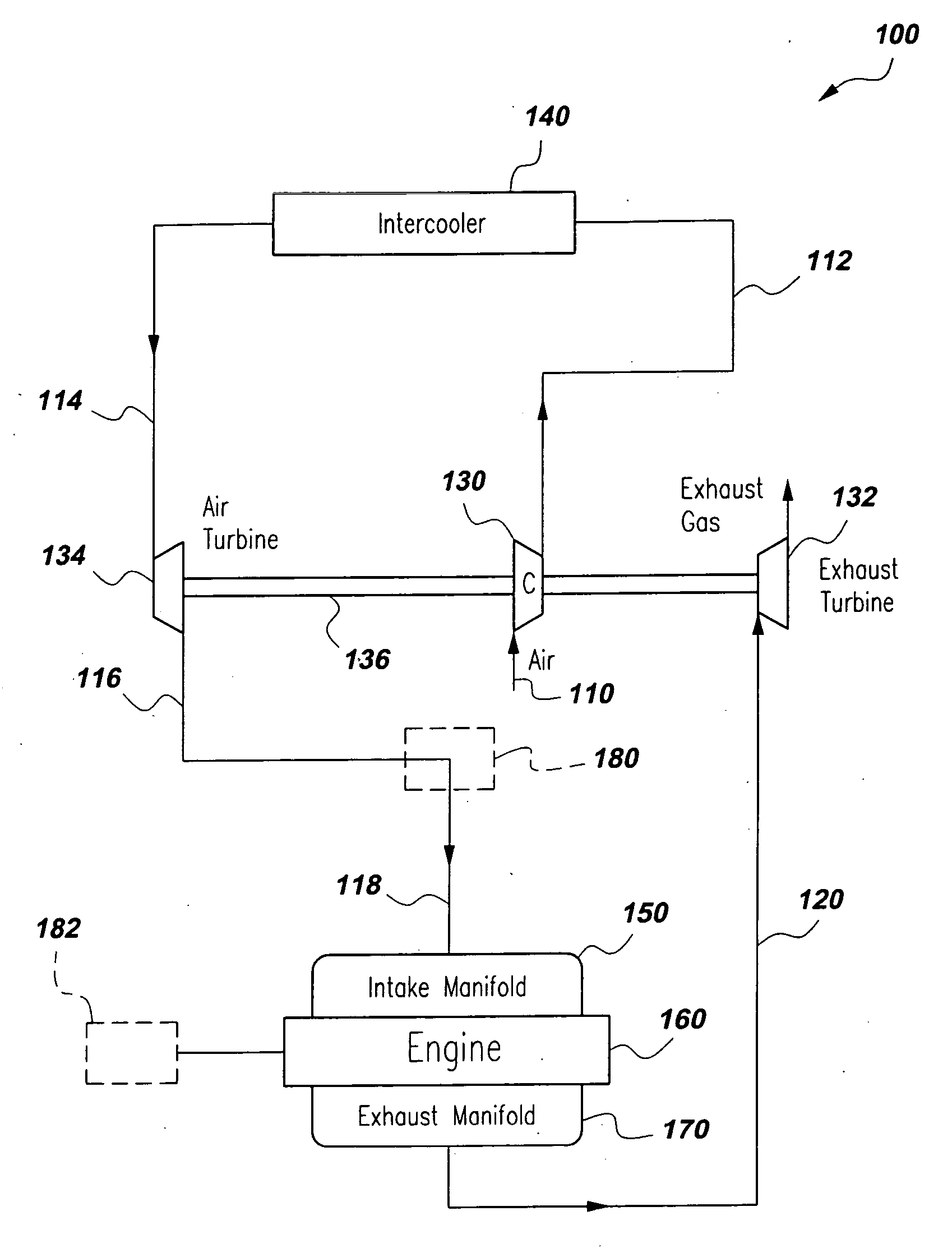
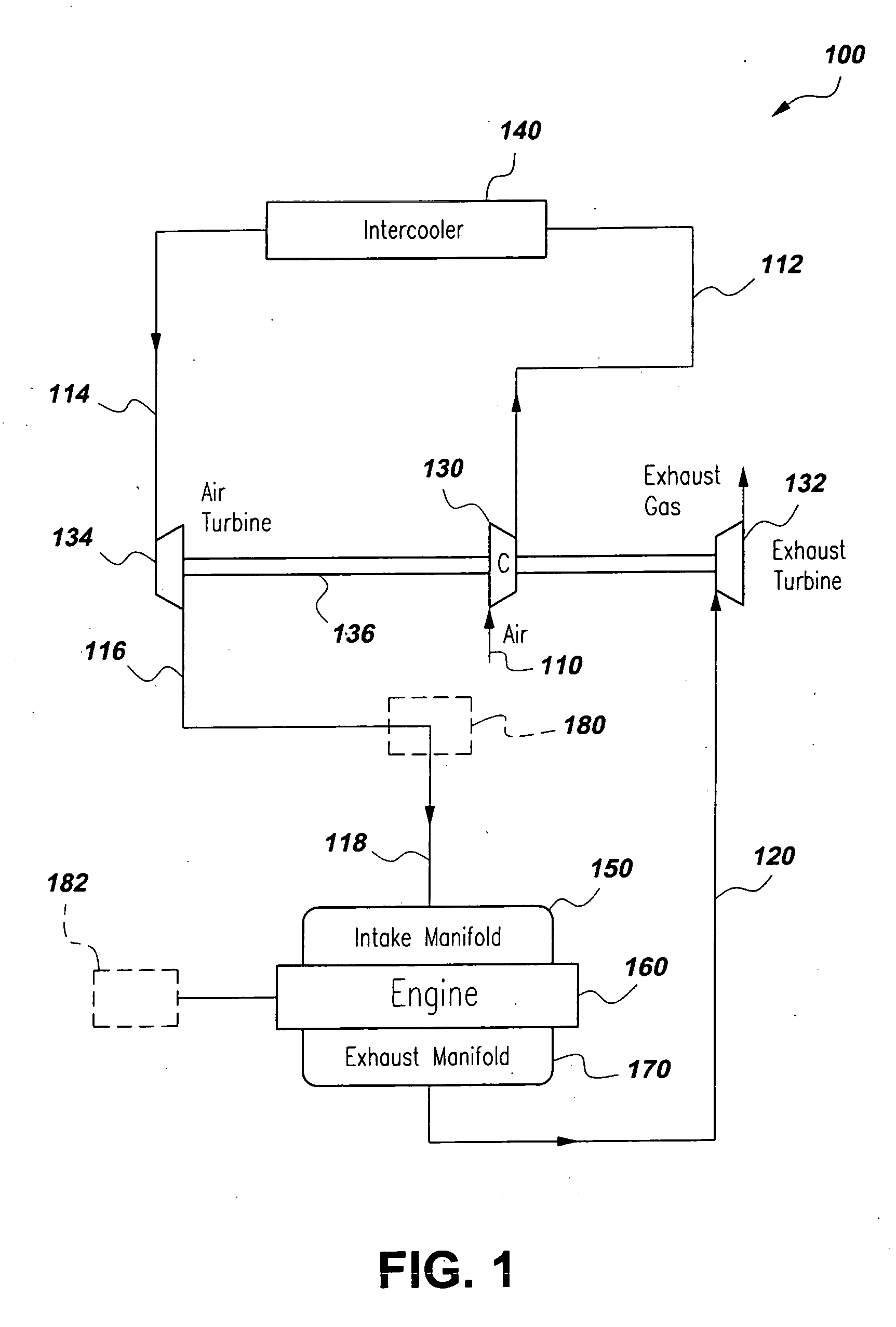
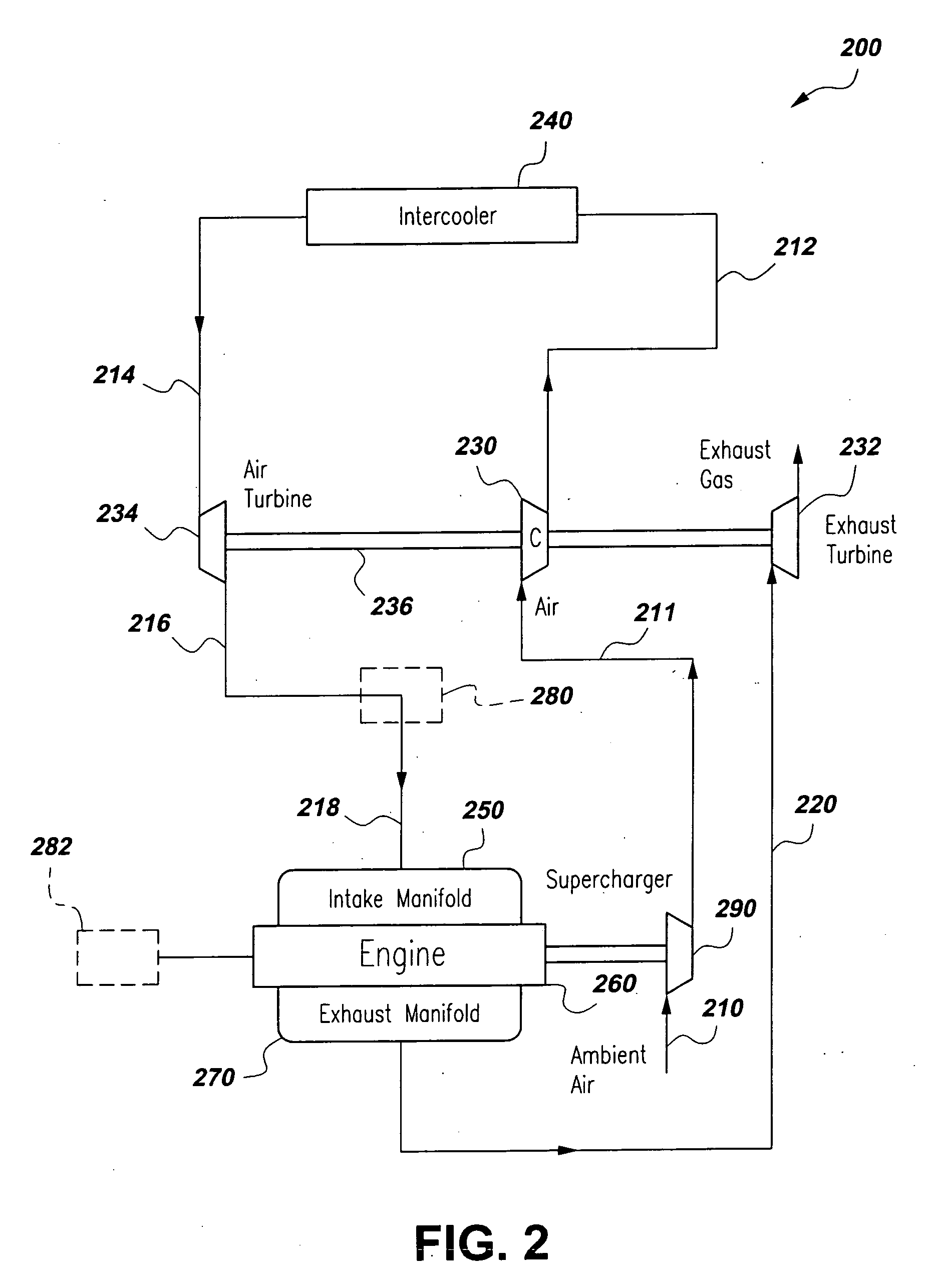
[0035] The present invention provides a turbocharged-intercooled engine utilizing the turbo-cool principle and method for operating the same. A turbocharged intercooled engine according to the present invention operates according to the turbo-cool principle. The engine has an air turbine for turbo-expansion cooling. The air turbine is coupled to a compressor so intake air pressure loss as a result of turbo-expansion is partially compensated by pressure gain due to the compression process. This use of an air turbine and its coupling to a compressor define the essence of the turbo-cool principle.

[0036] A better understanding of the method can be obt...


PUM


Abstract

A turbocharged-intercooled engine utilizing the turbo-cool principle and method for operating the same. The engine has an air turbine for turbo-expansion cooling. The air turbine is coupled to a compressor so intake air pressure loss as a result of turbo-expansion is partially compensated by pressure gain due to the compression process. This use of an air turbine and its coupling to a compressor define the essence of the turbo-cool principle.

Description

CROSS REFERENCE TO RELATED APPLICATIONS [0001] This application is a continuation-in-part of an application filed in the United States Patent and Trademark Office (USPTO) on Jun. 17, 2005 and assigned Ser. No. 11 / 155,862, that claims priority under 35 U.S.C. § 119 to applications filed in the USPTO on Jul. 22, 2004 and assigned Ser. No. 60 / 590,100, and on Jun. 17, 2004 and assigned Ser. No. 60 / 580,493, the contents of each of which are incorporated herein by reference. This application also claims priority under 35 U.S.C. § 119 to applications filed in the USPTO on Oct. 19, 2005 and assigned Ser. No. 60 / 728,223, and on Mar. 9, 2006 and assigned Ser. No. 60 / 780,729, the contents of each of which are incorporated herein by reference.BACKGROUND OF THE INVENTION [0002] 1. Field of the Invention [0003] The present invention generally relates to turbocharged internal combustion engines and, more particularly, to a turbocharged-intercooled engine utilizing the turbo-cool principle and meth...

Claims


Application Information

Patent Timeline
Patent Type & Authority Applications(United States)
IPC IPC(8): F02B33/44F02B29/04
CPCF02B29/04F02B37/00Y02T10/144Y02T10/146F02B37/04Y02T10/12
Inventor WANG, LIN-SHUYANG, SHIYOU
Owner WANG LIN SHU
Learn More