Fire suppression system

a fire suppression system and fire suppression technology, applied in boring tools, medical science, dentistry, etc., can solve the problems of high cost of heavy duty piping and damage to the environment, and achieve the effect of reducing pressur

Active Publication Date: 2007-02-15
KIDDE IP HLDG
View PDF7 Cites 21 Cited by
  • Summary
  • Abstract
  • Description
  • Claims
  • Application Information

AI Technical Summary

Benefits of technology

[0006] According to a first aspect of the present invention, there is provided a system for discharging inert gas for extinguishing or suppressing a fire, including fluid discharge control means for being positioned in a fluid flow path between a pressurised inert gas supply and a target fire suppression zone for reducing the pressure in the fluid flow path downstream of the fluid discharge control means without reference to the pressure in the fluid flow path upstream of the fluid discharge control means.
[0007] Advantageously this system is operable to reduce the peak pressure in the fluid flow path when the pressurised inert gas supply is initially discharged. The control means may reduce the applied pressure reduction after the initial discharge stage, when the pressure in the inert gas supply is lower. The pressure in the fluid flow path downstream of the control means is maintained generally constant—or at least below a maximum pressure that would be present in the absence of the control means.
[0011] According to a second aspect of the present invention, there is provided a system for discharging inert gas for extinguishing or suppressing a fire, in which the inert gas is stored in a plurality of pressurised containers, the system including a fluid discharge control means for being positioned in a fluid flow path between said plurality of pressurised containers and a target fire suppression zone for reducing the pressure in the fluid flow path downstream of the fluid discharge control means.
[0012] Advantageously this system is operable to reduce the peak pressure in the fluid flow path when the pressurised inert gas supply is initially discharged. The control means may reduce the applied pressure reduction after the initial discharge stage, when the pressure in the inert gas supply is lower. The pressure in the fluid flow path downstream of the control means is maintained generally constant—or at least below a maximum pressure that would be present in the absence of the control means.
[0015] According to a third aspect of the present invention, there is provided a method of discharging inert gas for extinguishing or suppressing a fire, including providing fluid discharge control means positioned in a fluid flow path between a pressurised inert gas supply and a target fire suppression zone for reducing the pressure in the fluid flow path downstream of the fluid discharge control means without reference to the pressure in the fluid flow path upstream of the fluid discharge control means.
[0016] According to a fourth aspect of the present invention, there is provided a method of discharging inert gas for extinguishing or suppressing a fire, in which the inert gas is stored in a plurality of pressurised containers, the method including providing a fluid discharge control means positioned in a fluid flow path between said plurality of pressurised containers and a target fire suppression zone for reducing the pressure in the fluid flow path upstream of the fluid discharge control means.

Problems solved by technology

Inert gas fire suppression systems are being used to replace systems using Halon suppressants because such Halon-based systems are considered to be damaging to the environment.
Such heavy duty piping is expensive.

Method used


Image

  • Fire suppression system
  • Fire suppression system
  • Fire suppression system

Examples


first embodiment

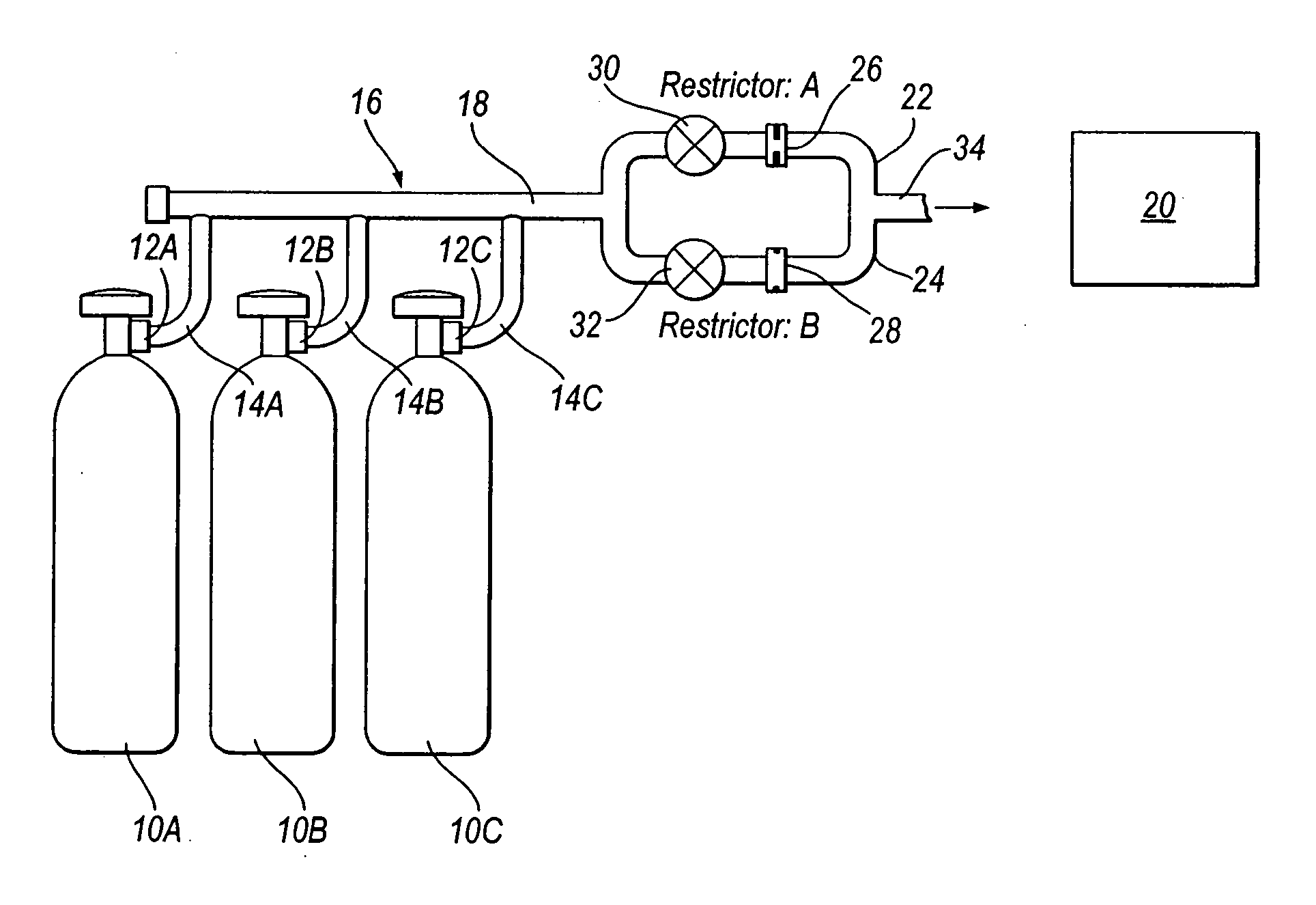
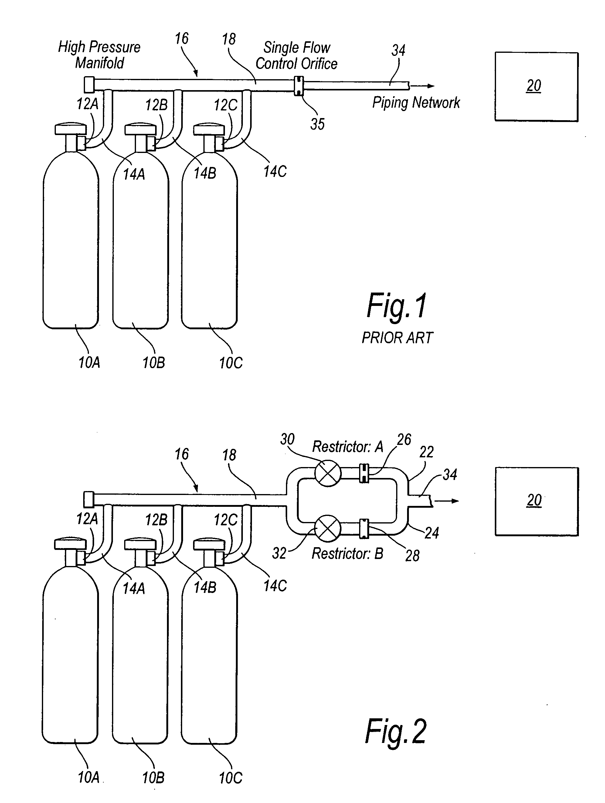
[0026]FIG. 2 shows the invention. Three containers 10A,10B,10C each contain inert gas stored at very high pressure. In the embodiment only three containers are shown, although it should be appreciated that many more containers may be employed, the number of containers being selected according to the application. In the embodiment, each of the containers contains a blend of 50% argon and 50% nitrogen, and may comprise Argonite (RTM) fire suppressant available from Kidde. The fire suppressant may be stored in the containers at a pressure of between 200 and 300 bar(g). The type and proportion of inert gases within the containers, and the pressure at which the inert gas is stored in the containers, will be determined in accordance with the application of the fire suppression system.

[0027] Each of the containers 10A, 10B and 10C is provided with a check valve 12A,12B,12C which, when opened, enables discharge of the inert gas from each of the containers into respective inlet pipes 14A,14B...

second embodiment

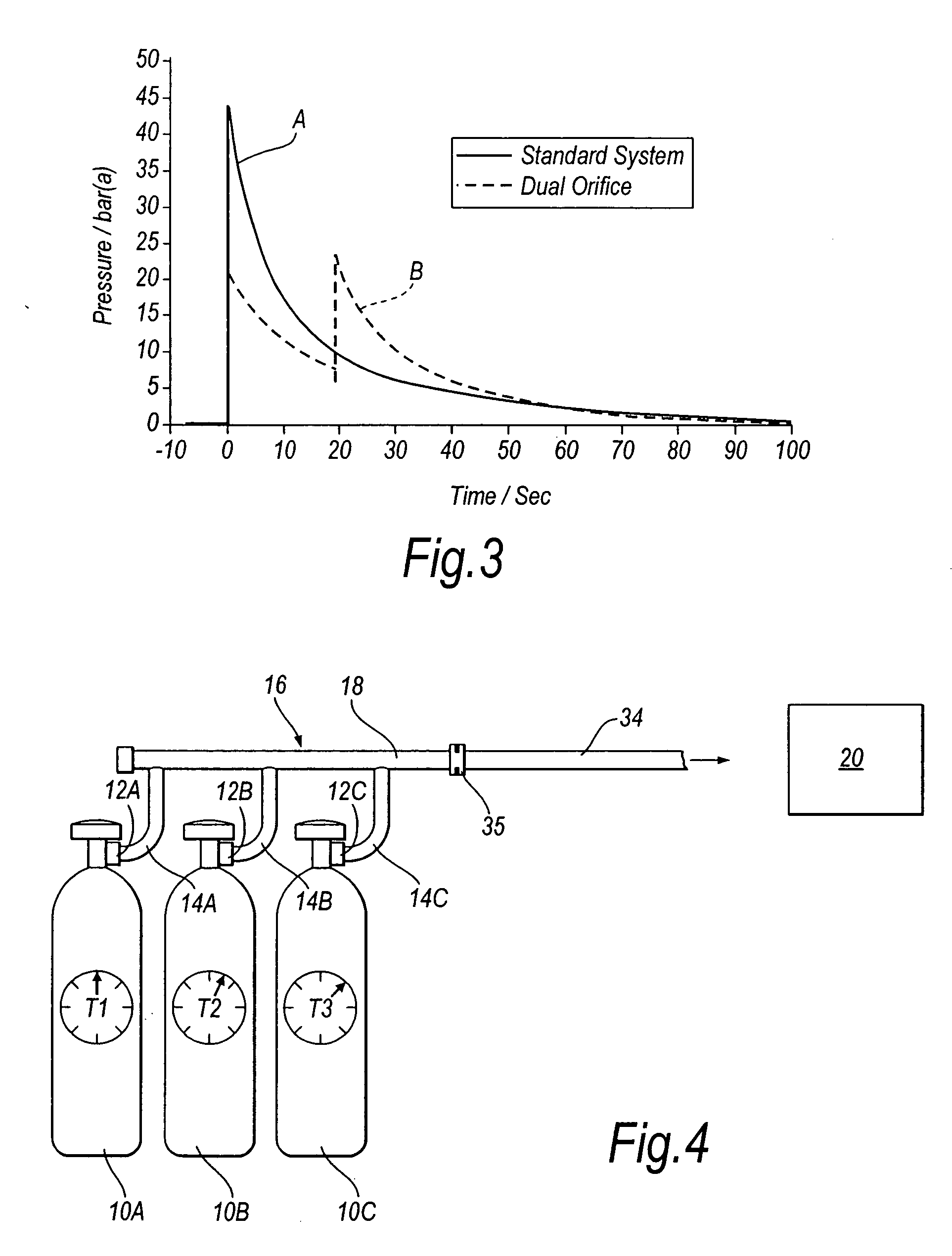
[0041] The check valve 12A of container 10A is opened to initiate fire suppression (T=0), with the check valves 12B and 12C remaining closed. This results in the first peak shown in the graph of FIG. 5. After a delay of 3.95 seconds (T=3.95 s) the check valve 12B is opened (with the check valve 12A remaining open and the check valve 12C being closed). This results in the second peak shown in the graph of FIG. 5. After a time delay of 17.1 seconds (T=17.1 s) from fire suppression initiation, the check valve 12C of the third container 10C is opened (with the check valves 12A and 12B also remaining open). This results in the third peak shown in the graph of FIG. 5. The peak nozzle pressure in the system of the second embodiment shown in FIG. 4 is 12.6 bar (g), which is a 40% reduction compared to the known system of FIG. 1.

[0042] Although in the FIG. 4 embodiment only three containers 10A,10B,10C are shown, it should be understood that more or fewer containers might be employed, depend...

third embodiment

[0045] In a third embodiment, shown in FIG. 6, the inert gas suppression system of FIG. 1 is modified so that the inlet pipe 14A,14B,14C of each container 10A,10B,10C is provided with a respective restrictor 40A,40B,40C. The restrictors 40A,40B,40C may be provided downstream of the check valve 12A,12B,12C at each container.

[0046] The size of each restrictor 40A,40B,40C may be determined by calculating an area equal to one third of that of the restrictor used for the three cylinder known standard system (i.e. the 12 millimeter restrictor used in the system shown in FIG. 1 equated to three 6.93 millimeter individual restrictors in the FIG. 6 embodiment, with a 7 millimeter restrictor being sufficient). The same logic can be applied to a two cylinder system with a 10 millimeter restrictor, with the individual restrictors having a diameter of 7.07 millimeters (with 7 millimeters being sufficient). The same restrictor size can be used for each of the cylinders 10A,10B,10C of a fire suppr...


PUM


Abstract

A system for discharging inert gas for extinguishing or suppressing a fire is disclosed. A fluid discharge control arrangement is positioned in a fluid flow path between a pressurised gas supply 10 A, 10 B, 10 C and the target fire suppression zone 20 . The fluid discharge control arrangement reduces the pressure in the fluid flow path downstream thereof. This may allow the downstream pipework to be selected to withstand a lower pressure than in a conventional system in which the fluid discharge control device was not provided, thereby reducing costs. The fluid discharge control device may comprise a first valve 30 and first restrictor 26 in the first flow path 22 and a second valve 32 and a second restrictor 28 provided in the second flow path 24 . Fluid from the containers 10 A, 10 B, 10 C flows initially through flow path 24 and restrictor 26 . Subsequently flow path 22 may be closed by optional valve 30 , and flow path 24 is opened by valve 32 . Fluid flow then passes through restrictor 28 . This reduces the peak pressure in the downstream pipework 34 . In another embodiment the discharge of inert gas from the containers 10 A, 10 B and 10 C is staggered to reduce the peak pressure in pipeline 34 . A further embodiment provides a restrictor in the inlet 14 A, 14 B, 14 C from each of the containers 10 A, 10 B, 10 C to the manifold 16 , thereby also reducing the peak pressure in the pipeline 34.

Description

FIELD OF THE INVENTION [0001] The present invention relates to a system and method for discharging an inert gas for extinguishing or suppressing a fire. BACKGROUND ART [0002] Inert gas fire suppression systems are being used to replace systems using Halon suppressants because such Halon-based systems are considered to be damaging to the environment. Systems using inert gas are generally required by safety standards to deliver inert gas to a room or other target zone so that the inert gas occupies approximately 40% by volume of the room. This lowers the oxygen level within the room to about 10 to 15%, which starves a fire of oxygen. The safety standards generally require that 95% of the required amount of inert gas is delivered to the protective room within sixty seconds. Preferably, the inert gas is selected so as not to be harmful to any occupants of the room, and may be so selected that the atmosphere in the room is breathable even after deployment of the fire suppressant gas. [00...

Claims


Application Information

Patent Timeline
Patent Type & Authority Applications(United States)
IPC IPC(8): A62C35/00A62C99/00
CPCA62C99/0027
Inventor ANDERSEN, THOMAS DAHLJENSEN, PETER O.LADE, ROBERTDUNSTER, ROBERTDAVIES, SIMON
Owner KIDDE IP HLDG
Why Eureka
Try Eureka