Magnetic valve for shock absorbers

a technology of shock absorber and magnetic valve, which is applied in the direction of shock absorber, steering device, cycle equipment, etc., can solve the problems of loss of pedaling efficiency, limited sensitivity of the damper, and limited potential of the flow-sensitive shim to distinguish between bumps and movements of the vehicle chassis, so as to improve the suspension performance

Active Publication Date: 2007-02-15
EKO SPORT
View PDF14 Cites 90 Cited by
  • Summary
  • Abstract
  • Description
  • Claims
  • Application Information

AI Technical Summary

Benefits of technology

[0014] The ability of a suspension damper to control unwanted chassis movements and yet compliantly absorb bumps is enhanced by the present invention insofar as damper valve closure in the invention is maintained by a force that moderates as the valve opens. The higher the force holding the valve in the closed position, the less unwanted chassis movement will occur. However, the lower the force urging closure of the valve once the valve opens, the longer the period of hydraulic fluid flow during

Problems solved by technology

Though superior to simple orifice dampers, dampers with flow-sensitive shims have limited potential for distinguishing between bumps and movements of the vehicle chassis.
Conventional suspension damping allows unwanted “bobbing” of the bicycle and loss of pedaling efficiency when the rider's weight shifts in this way.
Although a preloaded, sprung damper valve may open along a gently sloping load vs. deflection plot once its force threshold is reached, its sensitivity nevertheless is limited by the continued upward direction of the gradient.
But this acceleration, with its attendant peak pressure, fades long before the wheel finishes surmounting the bump, thereby allowing the valve to close prematurely under the countervailing force of the spring.
As this transmission of bump force increases, the ride becomes harsher and the vehicle's traction over irregular surfaces becomes poorer.
Similarly, in the case of rapid extension of a shock in which the rebound damping circuit is governed by a preloaded, sprung

Method used


Image

  • Magnetic valve for shock absorbers
  • Magnetic valve for shock absorbers
  • Magnetic valve for shock absorbers

Examples


Embodiment Construction

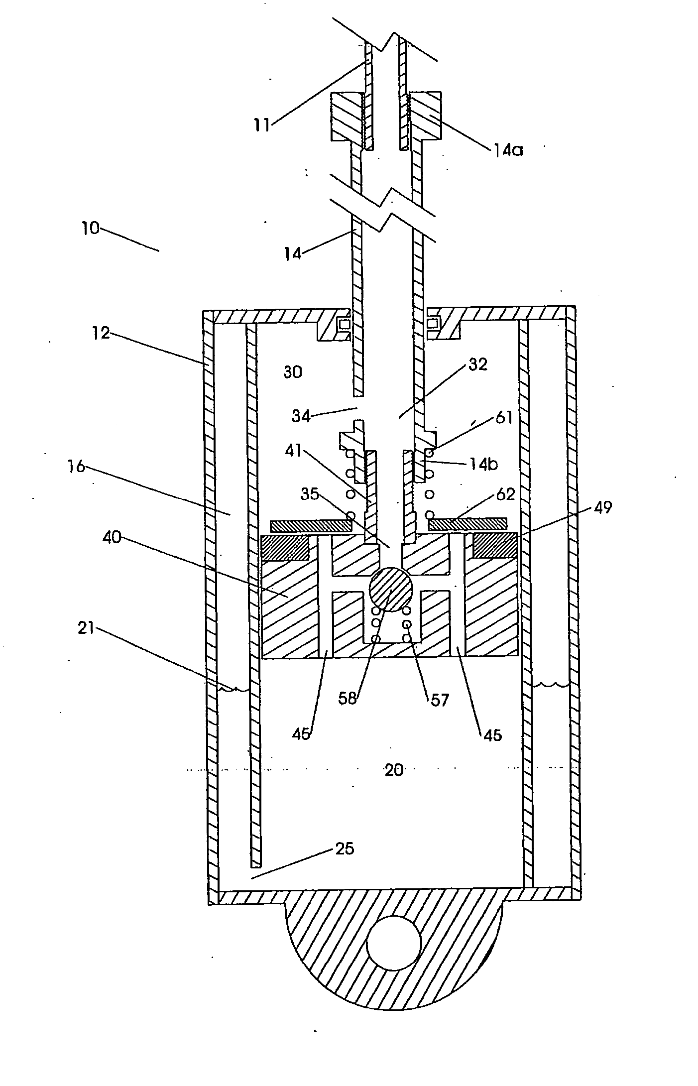
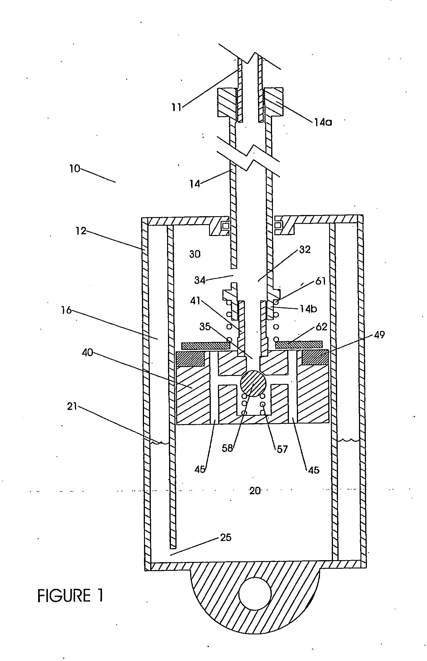
[0031]FIG. 1 shows the basic components of the shock absorber damper 10 including the cylindrical housing 12, the piston rod 11 and piston 40. The double wall of the housing forms the compartment 16 that contains a gas or other compressible medium that permits the level of fluid in the reservoir 21 to vary with displacement of fluid from chamber 20 through the port 25 as the piston rod enters the housing. This is described more fully below.

[0032] The velocity at which the piston 40 can move further into the housing under a given load is partly governed by the rate at which oil or other hydraulic fluid can flow from the compression chamber 20 through the port 45 in the piston 40, thence past the compression shim 62 and into the rebound chamber 30. It will become apparent that the compression shim 62 serves as part of a valve that is biased into the closed position by magnetic attraction between the shim 62 and the ring 49 embedded in the piston. These cooperating components tend to ...


PUM


Abstract

A shock absorber having a valve controlling the flow rate of fluid between a compression chamber and a rebound chamber in a housing and separated by a piston. The valve has an orifice component and a blocker component, one of which has a permanent magnet, and the other of which has a magnetically permeable material. Upon the application of sufficient fluid pressure, the blocker component is forced away from the orifice component, despite the magnetic bias that tends to attract the two structures. Because the magnetic force decreases as the two components are spaced farther apart, the shock absorber has excellent performance characteristics. Alternatively, a mechanical spring urges the blocker closed, and magnetic attraction between the blocker and a spaced opener mitigates the increased force of the compressed spring tending to close the valve.

Description

(e) BACKGROUND OF THE INVENTION [0001] 1. Field of the Invention [0002] The invention relates generally to suspension components on vehicles, and more particularly to a shock absorber with a damper valve that incorporates magnetic bias to improve valve performance. Such a device may be referred to as a threshold valve. [0003] 2. Description of the Related Art [0004] Conventional shock absorbers employ a piston in a cylinder containing a substantially incompressible fluid. Orifices in the piston and passages leading to a fluid reservoir regulate the flow of oil so as to damp the oscillation of a suspension spring. In more advanced designs, the orifices include sprung valves, which commonly take the form of holes covered by flexible shims made of elastically deformable material, such as spring steel. Valves of this design open progressively with greater force and can be used to damp low-speed compression and / or extension of shock absorbers while preventing pressure “spikes” and conseq...

Claims


Application Information

Patent Timeline
IPC IPC(8): F16F9/34
CPCF16F9/34F16F2222/06F16F9/461
Inventor BAREFOOT, DAREK C.
Owner EKO SPORT
Why Eureka
Try Eureka