Supercharger with electric motor

a supercharger and electric motor technology, applied in the direction of positive displacement liquid engines, electric generator control, piston pumps, etc., can solve the problems of reducing reliability, sucked into the engine, and lowering the compression efficiency of the supercharger, so as to simplify the cooling system, suppress the effect of weight increase and simplify the cooing system

Active Publication Date: 2007-02-15
IHI CORP
View PDF24 Cites 38 Cited by
  • Summary
  • Abstract
  • Description
  • Claims
  • Application Information

AI Technical Summary

Benefits of technology

[0030] In accordance with the first aspect mentioned above of the present invention, since the electric motor is cooled by the first cooling structure portion, and the diffuser portion is cooled by the second cooling structure portion, it is possible to suppress or prevent the solidification and stack of the oil mist in the diffuser portion. Further, since the electric motor and the diffuser portion are cooled by the common cooling fluid, in the first cooling structure portion and the second cooling structure portion, it is not necessary to independently supply the cooling fluid to the respective cooling structure portions. Accordingly, even if the cooling structure portion is provided for cooling both the electric motor and the diffuser portion, it is possible to simplify the cooling system.
[0031] In accordance with the second aspect mentioned above of the present invention, since the electric motor is arranged at the position adjacent to the compressor impeller, and the cooling fluid flow path having the first cooling structure portion and the second cooling structure portion is formed around it, it is possible to achieve the cooling of the electric motor and the cooling of the diffuser portion by the single cooling system.
[0032] Accordingly, since

Problems solved by technology

Accordingly, there is a problem that it lowers a compression efficiency of the supercharger, and it causes a reduction of a reliability by extension.
Further, there is a problem that the carbonized layer is peeled off due to a thermal expansion difference between the compressor housing and the carbonized layer, a vibration of the engine or the like, and there is a risk that it is sucked into the engine.
As mentioned above, in the supercharger on which the electric motor is not mounted, there has been proposed the technique of preventing the solidification and stack of the oil mist in the diffuser portion, however, the similar technique has not been proposed in the supercha

Method used


Image

  • Supercharger with electric motor
  • Supercharger with electric motor
  • Supercharger with electric motor

Examples


Embodiment Construction

[0038] A description will be in detail given below of a preferable embodiment in accordance with the present invention with reference to the accompanying drawings. In this case, the same reference numerals are attached to the common portions in each of the drawings, and an overlapping description will be omitted.

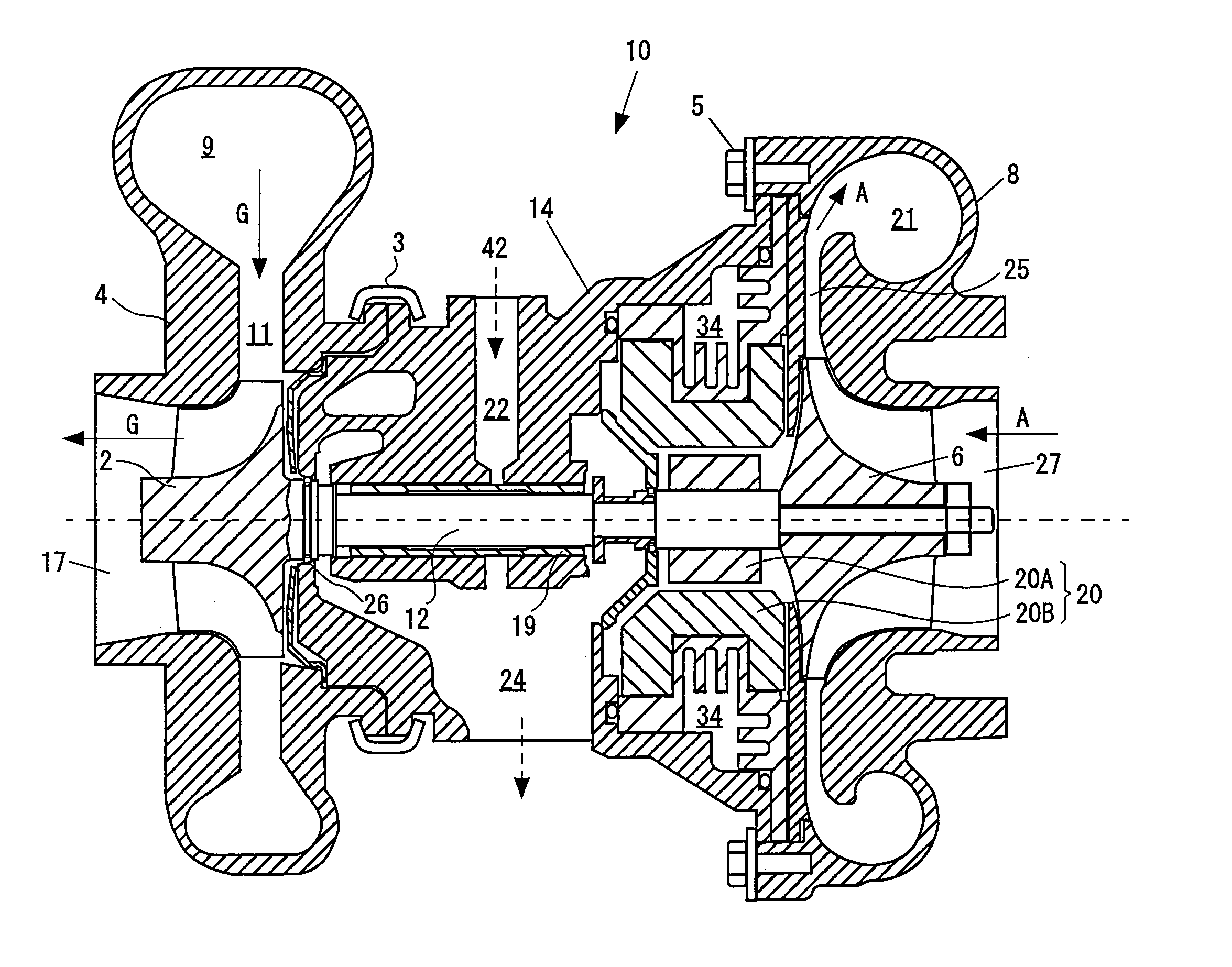
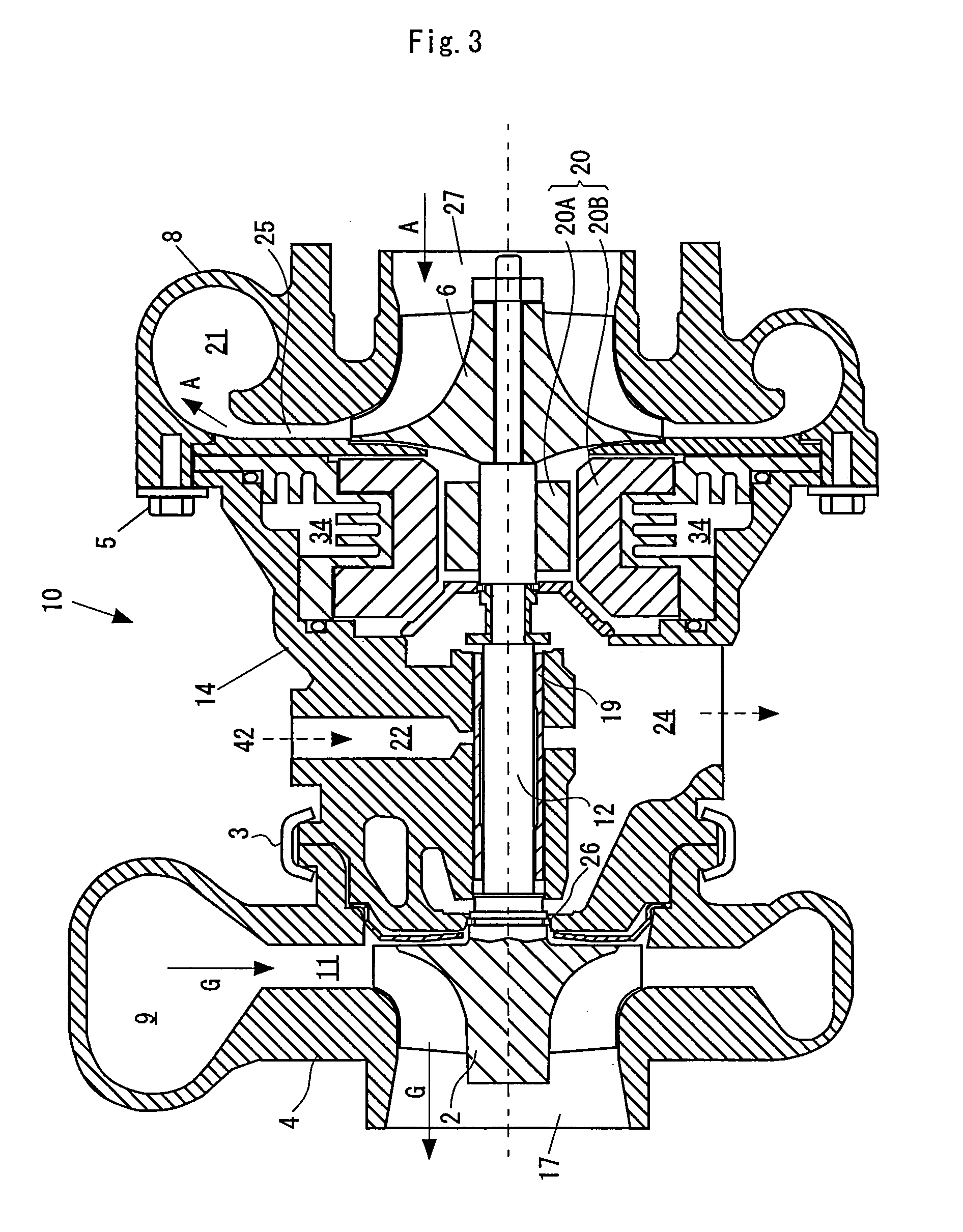
[0039]FIG. 3 is a cross sectional view of a supercharger with an electric motor in accordance with the embodiment of the present invention. As shown in FIG. 3, the supercharger 10 with the electric motor is constituted by constituting elements such as a turbine impeller 2, a turbine housing 4, a shaft 12, a compressor impeller 6, a compressor housing 8, an electric motor 20, a center housing 14 and the like.

[0040] In an exhaust passage side, there are arranged the turbine impeller 2 rotationally driven by an exhaust gas G of an internal combustion engine, and the turbine housing 4 surrounding the turbine impeller 2. The turbine housing 4 has a scroll chamber 9 formed aroun...


PUM


Abstract

In a supercharger (10) with an electric motor in accordance with the present invention, the electric motor (20) is arranged at a position adjacent to a compressor impeller (6), a center housing (14) has a cooling fluid flow path (34) formed in such a manner as to surround the electric motor (20) and be adjacent to a diffuser portion (25). A first cooling structure portion (38) is formed at a position in the electric motor (20) side in the cooling fluid flow path (34), a second cooling structure portion (39) is formed at a position in the diffuser portion (25) side in the cooling fluid flow path (34). The electric motor (20) is cooled by the first cooling structure portion (38). The diffuser portion (25) is cooled by the second cooling structure portion (39).

Description

BACKGROUND OF THE INVENTION [0001] 1. Field of the Invention [0002] The present invention relates to a supercharger with an electric motor, which has an electric motor assisting a rotational drive of a compressor in a supercharger driven by an exhaust gas of an internal combustion engine and compressing an intake air so as to supercharge. [0003] 2. Description of Related Art [0004] In order to improve a performance of an internal combustion engine, there has been widely used a supercharger (also called as “turbocharger”) driven by an exhaust gas of an internal combustion engine and compressing an intake air so as to supercharge. Further, there has been employed a supercharger with an electric motor in which an acceleration response or the like is improved by installing the electric motor on the same axis as a shaft of the supercharger and assisting a rotational drive of a compressor in an accelerated manner. [0005] The following patent document 1 discloses a prior art relating to th...

Claims


Application Information

Patent Timeline
IPC IPC(8): F04B17/00
CPCF01D25/125F02B37/10F02B37/14F02B39/005F05D2220/40F02B39/14F02C7/275H02K7/14Y02T10/144F02B39/10Y02T10/12
Inventor SHIBUI, YASUYUKISHIMIZU, MASAHIRO
Owner IHI CORP
Why Eureka
Try Eureka