Method for restoring portion of turbine component

a turbine component and a technology for restoring parts, applied in the direction of machines/engines, manufacturing tools, superimposed coating processes, etc., can solve the problems of high temperature durability of the components of the engine that must correspondingly increase, alloys alone are often inadequate to form turbine components located in certain sections, and can be susceptible to oxidation or other corrosion problems

Inactive Publication Date: 2007-02-22
GENERAL ELECTRIC CO
View PDF41 Cites 13 Cited by
  • Summary
  • Abstract
  • Description
  • Claims
  • Application Information

AI Technical Summary

Benefits of technology

[0015] (2) at least substantially restores the removed wall thickness.
[0021] (2) at least substantially restores the removed wall thickness.
[0022] The embodiments of the method of this invention provide a number of advantages and benefits with regard to restoring the wall thickness of airfoils, and in particular, repaired airfoils of turbine components. For example, the ability to be able to effectively restore the removed wall thickness of the repaired airfoil permits repair of protective coatings on such airfoils a plurality of times without adversely affecting the mechanical or other properties (e.g., mechanical strength) of the turbine component comprising the airfoil. The ability to be able to effectively restore the wall thickness of the repaired airfoil also avoids having to dispose of repaired turbine component (e.g., turbine blade) because of an insufficient wall thickness.

Problems solved by technology

However, as operating temperatures increase, the high temperature durability of the components of the engine must correspondingly increase.
While significant advances in high temperature capabilities have been achieved through formulation of nickel and cobalt-base superalloys, such alloys alone are often inadequate to form turbine components located in certain sections of a gas turbine engine, turbine shrouds, buckets, nozzles, combustion liners and deflector plates, augmentors and the like.
For example, turbine components such as turbine blades, vanes, etc., can be susceptible to oxidation or other corrosion problems when operating in certain sections of the gas turbine engine.
Though significant advances have been made in improving the durability of thermal barrier coatings, as well as diffusion coatings used for environmental protection, such coatings will typically require removal and repair under certain circumstances.
For example, thermal barrier coatings, as well as diffusion coatings, can be susceptible to various types of damage, including objects ingested by the engine, erosion, oxidation, and attack from environmental contaminants that will require removal and repair of the coating.
Removal of the coating may also be necessitated during turbine component manufacture because of defects in the coating, handling damage and the need to repeat noncoating-related manufacturing operations which require removal of the coating, e.g., electrical discharge machining (EDM) operations, etc.
Indeed, the wall thickness of the airfoil can become so thin that the turbine blade, vane, etc., is no longer useable and must therefore be scrapped or discarded.

Method used


Image

  • Method for restoring portion of turbine component
  • Method for restoring portion of turbine component
  • Method for restoring portion of turbine component

Examples


Embodiment Construction

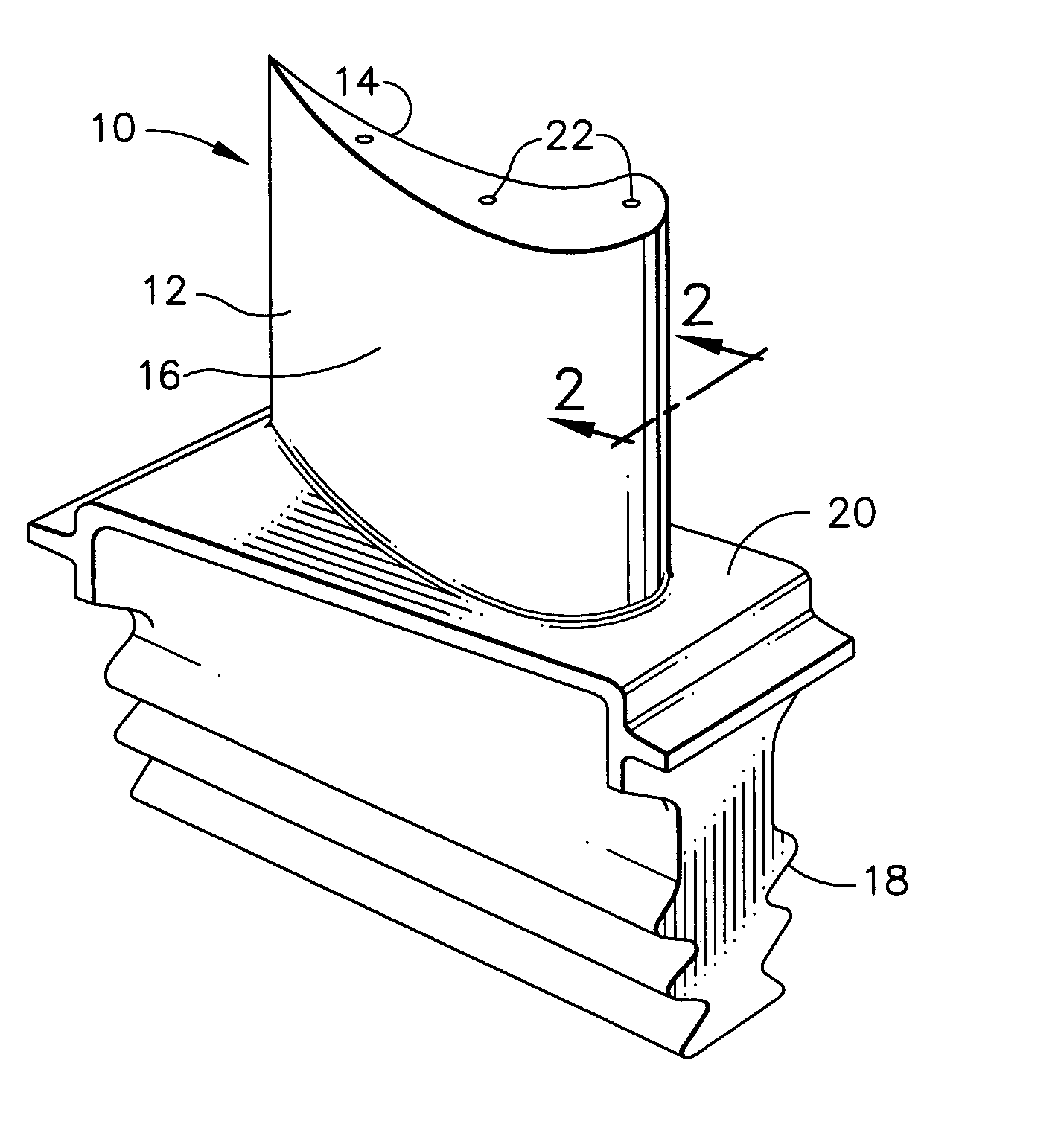
[0028] As used herein, the term “wall thickness” refers to the total thickness of the metal substrate in the wall of the airfoil.

[0029] As used herein, the term “repair area” refers to that area of the airfoil from which a coating, such as a diffusion coating, is removed, in whole or in part.

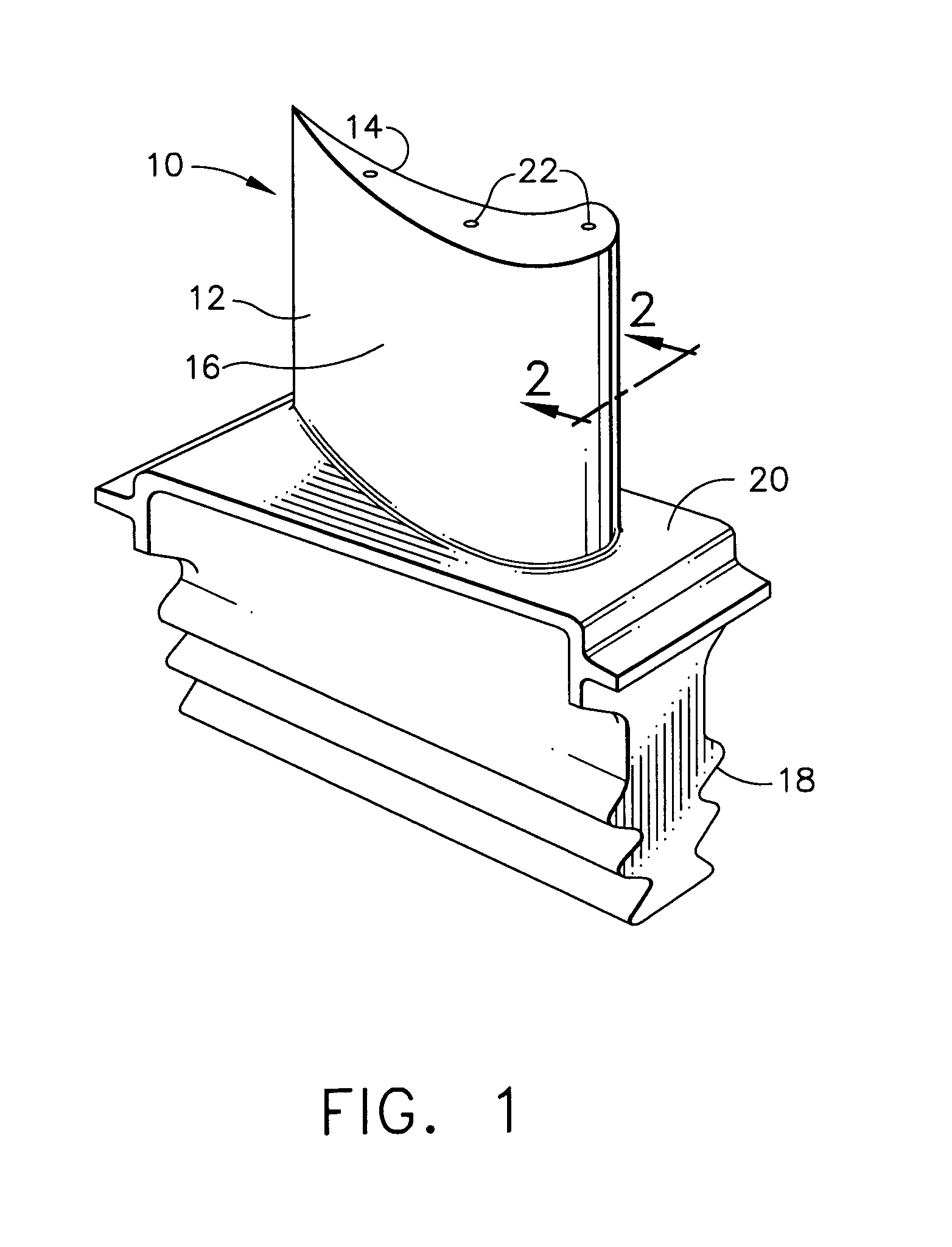
[0030] As used herein, the term “removed wall thickness” refers to that portion of the wall thickness of the metal substrate that is removed when the coating, such as a diffusion coating, is removed.

[0031] As used herein, the term “residual wall thickness” refers to that portion of the wall thickness of the metal substrate that remains after removal of the portion of the wall thickness.

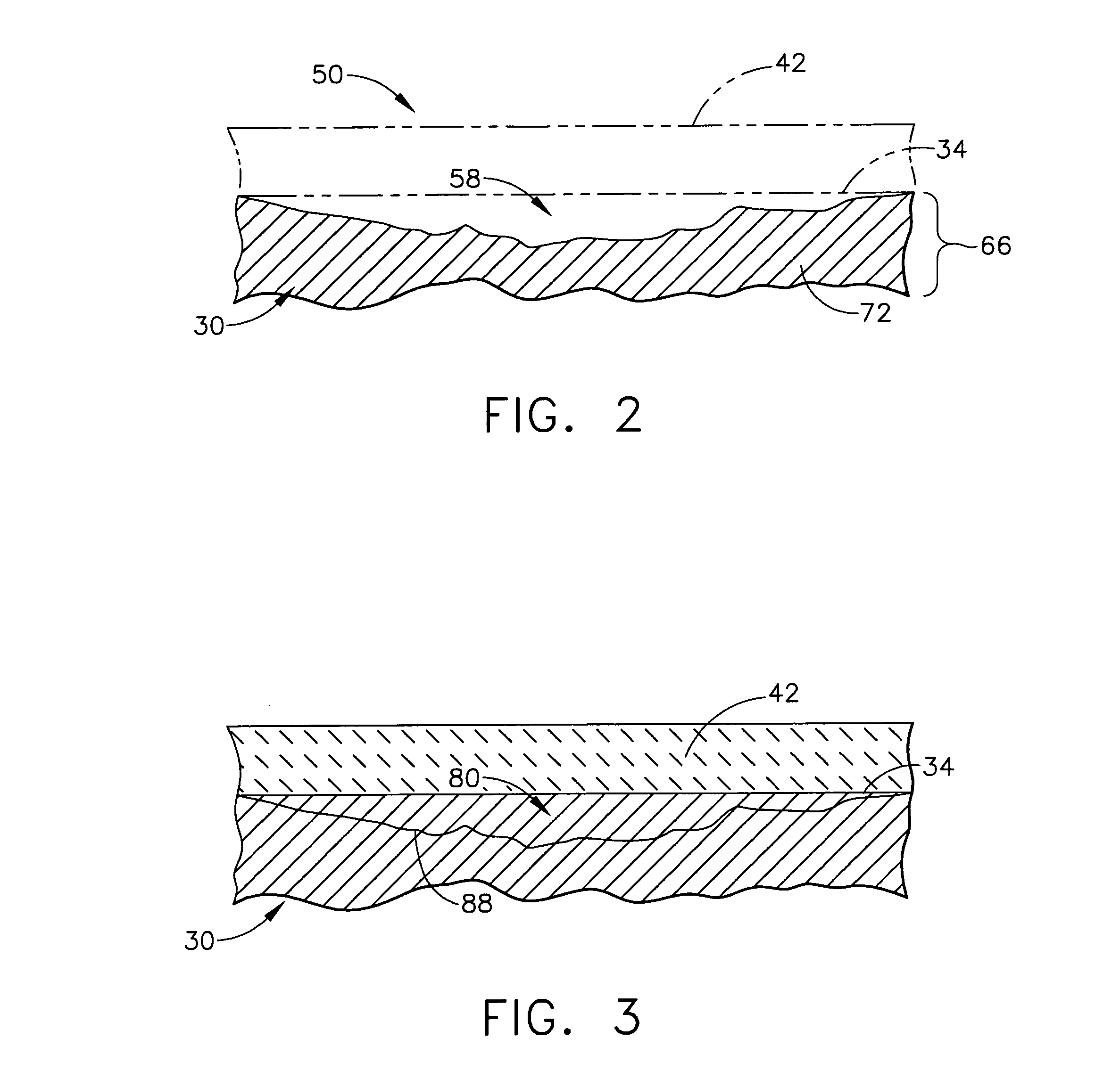
[0032] As used herein, the term “adhered to the residual wall thickness” refers to the applied metal composition becoming combined with, integral with, attached to or otherwise adhered to the residual wall thickness. Typically, the applied metal composition becomes integral with or substantially integral with ...


PUM

PropertyMeasurementUnit
particle sizeaaaaaaaaaa
thicknessaaaaaaaaaa

Abstract

A method for restoring a removed portion of the airfoil wall of a turbine component. This method comprises the following steps: (a) providing a turbine component comprising an airfoil having a metal substrate with a wall thickness, wherein a portion of the wall thickness has been removed so as to provide a residual wall thickness; (b) providing a metal composition that at least substantially matches that of the residual wall thickness; and (c) applying the metal composition to the residual wall thickness such that the metal composition: (1) is adhered to the residual wall thickness; and (2) at least substantially restores the removed wall thickness. Also provided is a method for restoring a removed portion of the airfoil wall of a previously repaired turbine component.

Description

BACKGROUND OF THE INVENTION [0001] This invention broadly relates to a method for restoring a removed portion of the airfoil wall of a turbine component. [0002] Higher operating temperatures of gas turbine engines are continuously sought in order to increase their efficiency. However, as operating temperatures increase, the high temperature durability of the components of the engine must correspondingly increase. While significant advances in high temperature capabilities have been achieved through formulation of nickel and cobalt-base superalloys, such alloys alone are often inadequate to form turbine components located in certain sections of a gas turbine engine, turbine shrouds, buckets, nozzles, combustion liners and deflector plates, augmentors and the like. A common solution is to thermally insulate such components, e.g., turbine blades, vanes, etc., in order to minimize their service temperatures. For this purpose, thermal barrier coatings have been applied over the metal sub...

Claims


Application Information

Patent Timeline
Patent Type & Authority Applications(United States)
IPC IPC(8): B23P6/00B23P19/04
CPCF01D5/005F01D5/288C23C28/321Y10T29/49737C23C28/3455Y10T29/49732Y10T29/49318C23C28/325
Inventor KELLY, THOMAS JOSEPH
Owner GENERAL ELECTRIC CO
Why Eureka
Try Eureka