Cutting tool insert

a cutting tool and insert technology, applied in the field can solve the problems of cutting tool inserts subjected to heavy loads and high temperatures, cutting tools subjected to large contact pressures, and their life, so as to reduce, preferably eliminate, the effect of spalling and/or chipping type wear and improved wear behaviour

Active Publication Date: 2007-02-22
BAKER HUGHES INC
View PDF46 Cites 91 Cited by
  • Summary
  • Abstract
  • Description
  • Claims
  • Application Information

AI Technical Summary

Benefits of technology

[0031] The invention extends to a method of reducing, preferably eliminating, spalling and/or chipping type wear in a polycrystalline diamond abrasive element susceptible to such wear, including the step of removing catalysing material from regions of the polycrystalline diamo

Problems solved by technology

In drilling operations, such a cutting tool insert is subjected to heavy loads and high temperatures at various stages of its life.
In the early stages of drilling, when the sharp cutting edge of the insert contacts the subterranean formation, the cutting tool is subjected to large contact pressures.
This results in the possibility of a number of fracture processes such as fatigue cracking being initiated.
As the cutting edge of the insert wears, the contact pressure decreases and is generally too low to cause high energy failures.
However, this pressure can still propagate cracks initiated under high contact pressures; and can eventually result in spalling-type failures.
In any drilling application, cutters may wear through a combination of smooth, abrasive type wear and spalling/chipping type wear.
Whilst a smooth, abrasive wear mode is desirable because it delivers maximum benefit from the highly wear-resistant PCD material, spalling or chipping type wear is unfavourable.
Even fairly minimal fracture damage of this type can have a deleterious effect on both cutting life and performance.
Once chipping begins, the amount of damage to the table continually increases, as a result of increased normal force now required to achieve a given depth of cut.
Therefore, as cutter damage occurs and the rate of penetration of the drill bit decreases, the response of increasing weight on bit can quickly lead to further degradation and ultimately catastrophic failure of the chipped cutting ele

Method used


Image

  • Cutting tool insert
  • Cutting tool insert

Examples


Embodiment Construction

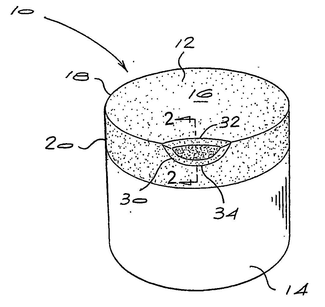
[0036] The polycrystalline diamond abrasive element of the invention has particular application as a cutter element for drill bits. In this application, it has been found to have excellent wear resistance and impact strength without being susceptible to spalling or chipping in either the leading edge or trailing edge of the typical wear scar. These properties allow it to be used effectively in drilling or boring of subterranean formations having high compressive strength.

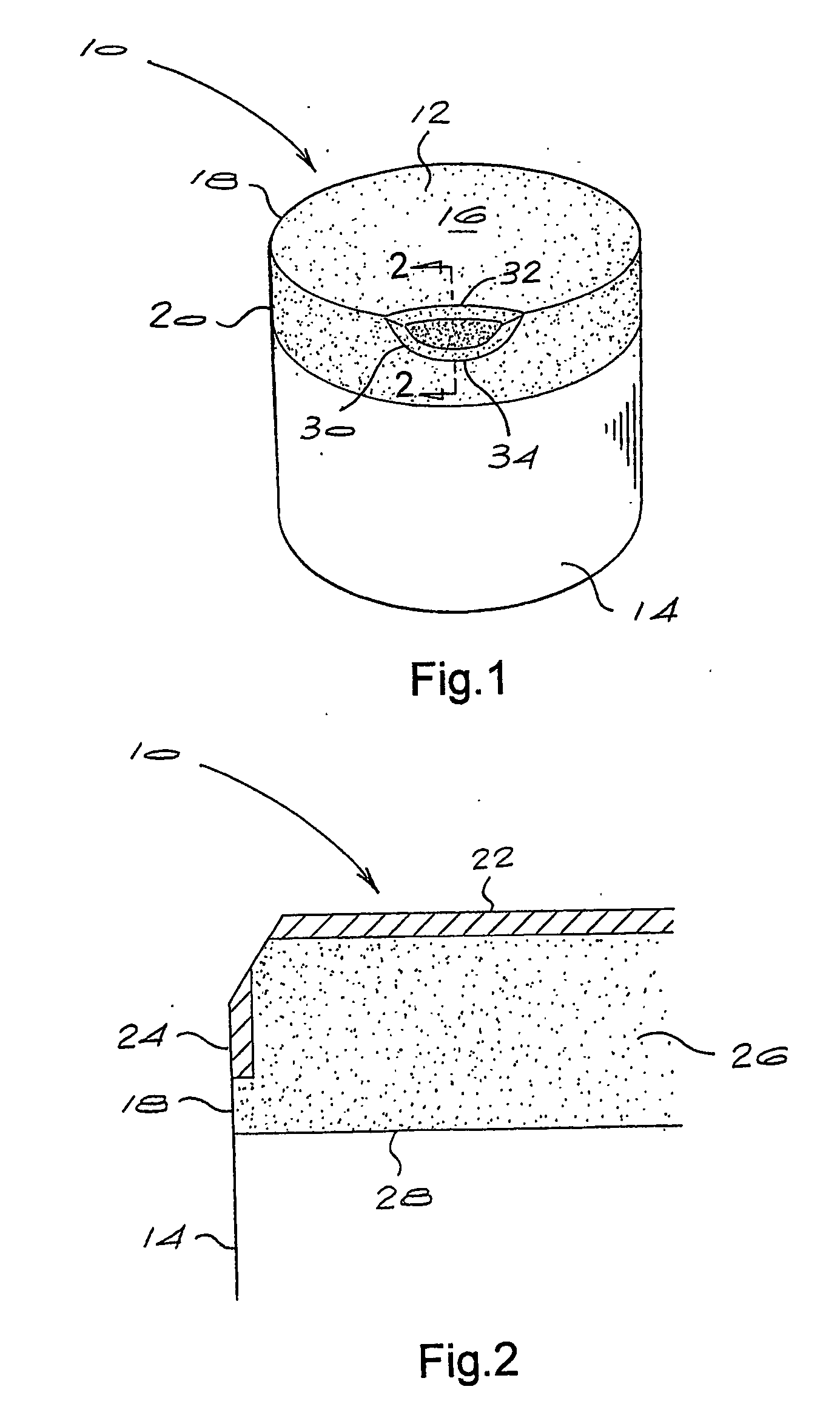
[0037] Referring to FIGS. 1 and 2 of the accompanying drawings, the cutting element 10 has a polycrystalline diamond layer 12, bonded to a substrate 14. The polycrystalline diamond layer has an upper working surface 16 around which is a peripheral cutting edge 18 and a peripheral surface 20. The polycrystalline diamond layer 12 has respective regions 22, 24 lean in catalysing material and a region 26 rich in catalysing material. The regions 22, 24 lean in catalysing material extend respectively from the working sur...


PUM

PropertyMeasurementUnit
Thicknessaaaaaaaaaa
Depthaaaaaaaaaa
Depthaaaaaaaaaa

Abstract

A polycrystalline diamond abrasive cutting element consists generally of a layer of high grade polycrystalline diamond bonded to a cemented carbide substrate. The polycrystalline diamond layer has a working surface and an outer peripheral surface and is characterized by having an annular region or a portion thereof adjacent the peripheral surface that is lean in catalysing material. A region adjacent the working surface is also lean in catalysing material such that in use, as a wear scar develops, both the leading edge and the trailing edge thereof are located in a region lean in catalysing material.

Description

BACKGROUND OF THE INVENTION [0001] This invention relates to tool inserts and more particularly to cutting tool inserts for use in drilling and coring holes in subterranean formations. [0002] A commonly used cutting tool insert for drill bits is one which comprises a layer of polycrystalline diamond (PCD) bonded to a cemented carbide substrate. The layer of PCD presents a working face and a cutting edge around a portion of the periphery of the working surface. [0003] Polycrystalline diamond, also known as a diamond abrasive compact, comprises a mass of diamond particles containing a substantial amount of direct diamond-to-diamond bonding. Polycrystalline diamond will generally have a second phase which contains a diamond catalyst / solvent such as cobalt, nickel, iron or an alloy containing one or more such metals. [0004] In drilling operations, such a cutting tool insert is subjected to heavy loads and high temperatures at various stages of its life. In the early stages of drilling, ...

Claims


Application Information

Patent Timeline
IPC IPC(8): E21B10/36B23BB23B27/14C23C30/00
CPCB23B27/148C23C30/005B23B2226/315B23B27/14B23B27/00
Inventor ACHILLES, ROY DERRICK
Owner BAKER HUGHES INC
Why Eureka
Try Eureka