

Tray apparatus, column with same and method of assembling and using
a tray apparatus and column technology, applied in the field of column tray apparatus, can solve the problems of preventing the inlet portion of the downcomer from being used effectively, too much momentum, etc., and achieve the effects of smooth flow through capability, high transfer efficiency, and more liquid handling capability
Inactive Publication Date: 2007-02-22
SULZER MANAGEMENT AG
View PDF22 Cites 16 Cited by
- Summary
- Abstract
- Description
- Claims
- Application Information
AI Technical Summary
Benefits of technology
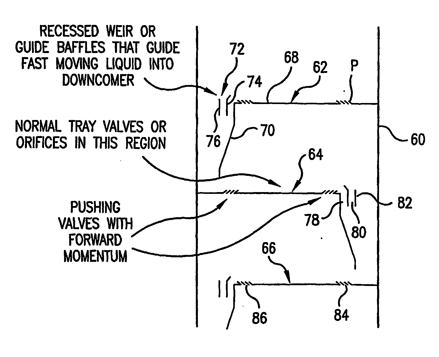
[0012] The present invention comprises a tray apparatus with a downcomer having suspended high momentum fluid flow redirecting means and a tray deck having a fluid momentum enhancing means that, through the use of its fluid momentum enhancing devices, exerts momentum on the liquid flowing horizontally across the tray with the goal being to provide for more liquid handling capability while retaining a high transfer efficiency and a smooth flow through capability. A suitable fluid momentum enhancing system includes push valves provided on the tray deck, and preferably arranged in zones or distribution patterns (e.g., increased ratio of push valves in the immediate vicinity (e.g., within 0 to 60 cm along a main flow direction line) of a baffled downcomer inlet alone or coupled with increased ratio push valve zone(s) just downstream (e.g., within 0 to 60 cm) of the tray's receiving area located below an upper tray apparatus downcomer outlet. This zoning facilitates an increase in momentum of the desired fluid off the tray and provides for a rapid clearing of fluid off the deck while providing also on efficient flow relationship with the means for redirecting the flow provided at the interface between the tray end (or edge if a non-end, interior downcomer) and the downcomer inlet. Thus, under the present invention, for use in combination with the aforementioned fluid momentum enhancing system, the present invention features a fluid flow redirecting assembly designed to transfer the horizontal momentum of the fluid being pushed by the fluid momentum enhancing means into downward momentum through a downcomer positioned between an upper tray and a lower reception tray below. The fluid flow redirecting assembly includes one or more flow redirecting devices, as in, for example, one or more recessed weir or shaped downcomer inlet guide vanes for facilitating the transfer of momentum through the downcomer (e.g., starting at the interface between the exit end of the tray deck and the inlet opening for the downcomer.) The redirecting assembly preferably including vanes that extend above the horizontal level of the tray and preferably also above the lower level of fluid and into a froth capture and redirect level (e.g., a 0 to 75 mm or more preferably 10 to 40 mm extension above the adjacent tray deck level). The preferred embodiment features inlet guide vanes that are designed to facilitate the transition of the fluid horizontal momentum to downward momentum through use, for example, of an upper curved infeed baffle section. The inlet guide vanes also preferably extend across the entire downcomer inlet end (or abut the entire circumference for circular downcomers or across the upper, open end of a whirlpool downcomer, and are supported by for example, the downcomer structure, the tray apparatus, the vessel or any combination of the same.
[0016] With the use of push valves in combination with the shaped downcomer guide vanes of the present invention, the horizontal momentum from the pushing valves is transformed into a controlled downward momentum by the guides. The channeling of this energy to make the liquid and / or froth go into the downcomer will allow more momentum to be imparted from the push valves and provide for the potential of higher capacity and performance than can be achieved by using these devices individually.
[0026] A non-solid (e.g., apertured) secondary guide vane provides for the introduction of the more fluid component to be directed into the less fluid component which can function to help support or knock down the level of frothing in the radial outer downcomer guide passages.
Problems solved by technology
Method used
View moreImage
Smart ImageViewing Examples

Examples
first embodiment
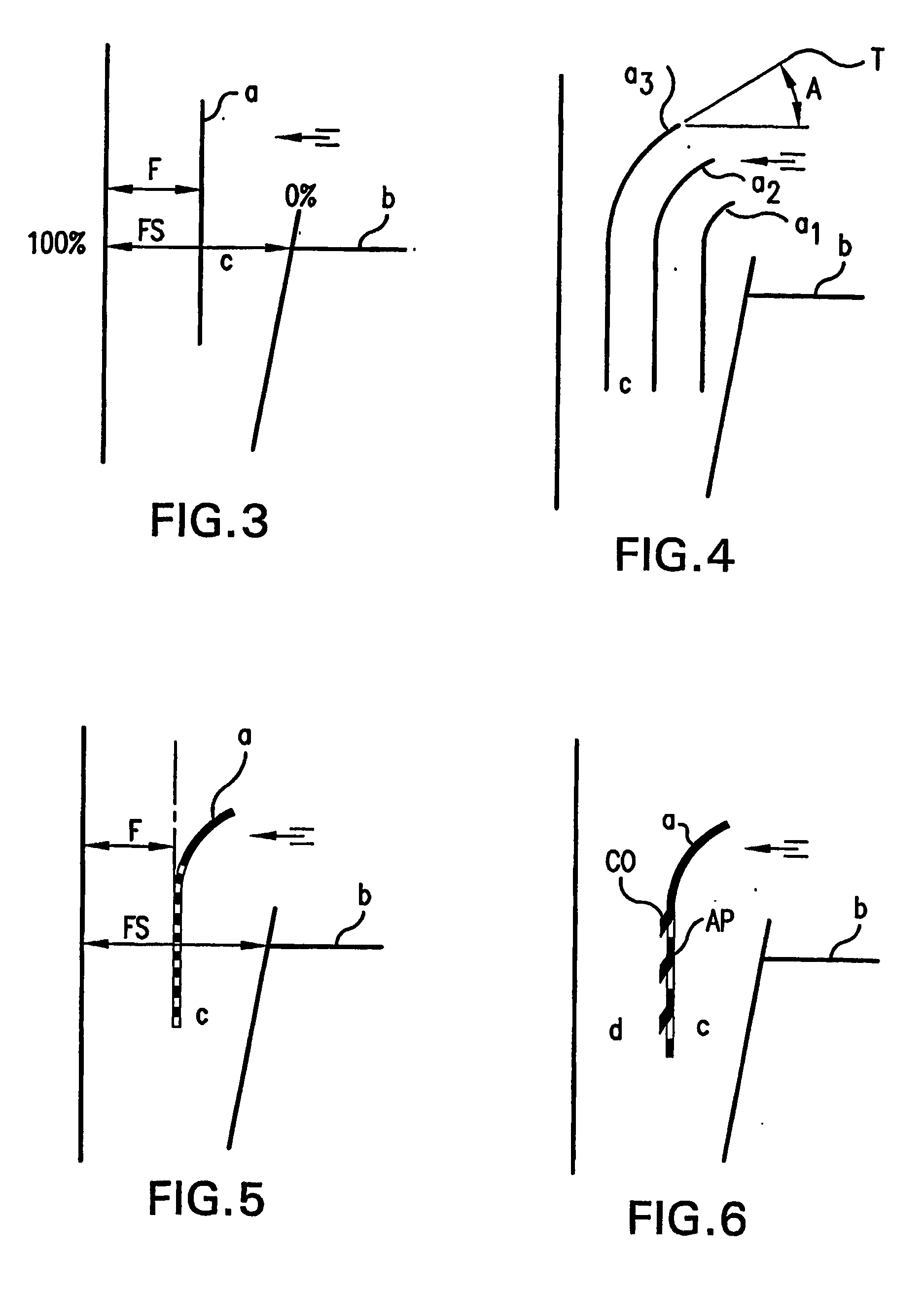
[0036]FIG. 3 shows a planar fluid flow redirecting device extending within an intermediate area of an end downcomer's inlet.
second embodiment
[0037]FIG. 4 shows a fluid flow redirecting device of the present invention with multiple upper end curved, spaced redirecting plates.
third embodiment
[0038]FIG. 5 shows a fluid flow redirecting device of the present invention featuring a top end curved baffle plate with porous vertical, intermediate (boundary curve) and lower plate extension.
Login to View More PUM
 Abstract
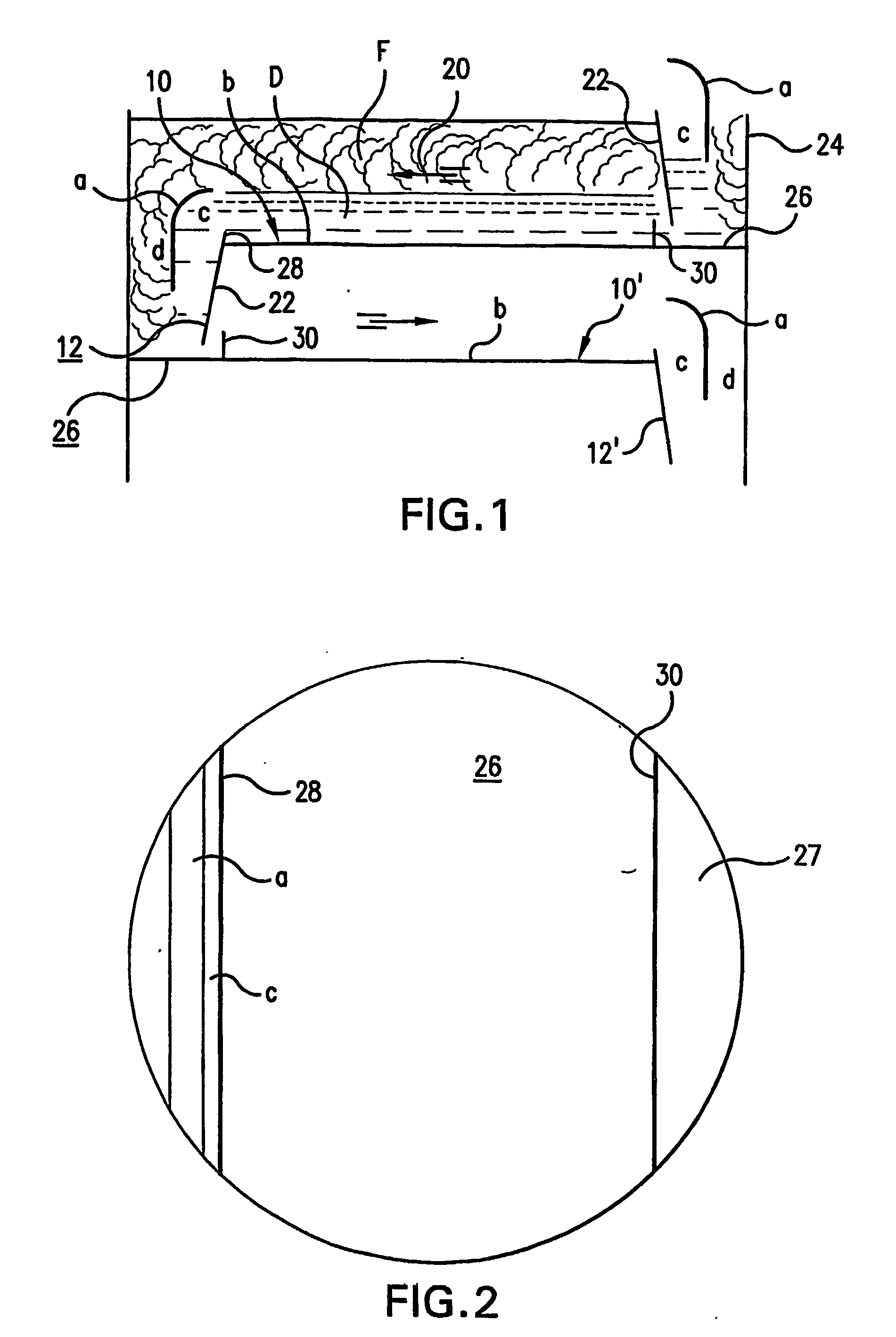
A vapor-liquid contact tray apparatus having a tray with a fluid infeed section and a fluid travel section together with downcomer which is in fluid communication with the fluid travel section of the tray. A redirecting baffle is positioned at an inlet opening of the downcomer and push valves are provided in the fluid travel section of the tray. The push valves are preferably arranged in one or more zones of high concentration of push valves relative to one or more bubbling aperture zones with a lower concentration of push valves or no push valves. The redirecting baffle is provided in the downcomer and extends above the tray to capture fluid flowing horizontally off of the tray (e.g., exiting from a weirless or weir interface) and into a preferably concave upper portion of the redirecting baffle for controlling and redirecting the high momentum flow into and through the downcomer. A plurality of redirecting baffles are featured in one embodiment together with apertured straight sections extending down into the downcomer as in down to the half way mark of downcomer depth or further down including out of the bottom of downcomer.
Description
PRIORITY [0001] The present invention claims priority under 35 USC §119(e) to U.S. Provisional Patent Application 60 / 445,253 filed Feb. 6, 2003, which application in incorporated herein by reference.FIELD OF THE INVENTION [0002] The present invention is directed at a column tray apparatus such as used in a distillation column, with a preferred embodiment featuring a downcomer and tray with push valves or flow momentum enhancing means combined with flow redirecting means, as in one or more recessed weirs or shaped downcomer inlet guide vanes, for receiving the fluid (e.g., vapor-liquid contact froth) with enhanced momentum and redirecting and discharging the fluid through the downcomer. This invention further relates to mass transfer and exchange columns and, to vapor-liquid contact trays employed within such columns. The invention is also directed at contact trays and methods of assembling and using column tray apparatus and columns with said tray apparatus. BACKGROUND [0003] Vapor-...
Claims
Login to View More Application Information
Patent Timeline
 IPC IPC(8): B01F3/04B01D3/20B01D3/22
CPCB01D3/22B01D3/20
InventorPILLING, MARK W.FISCHER, MARKUSMOSCA, GIUSEPPETACCHINI, ELENA
OwnerSULZER MANAGEMENT AG