Stepping motor control system and method for controlling a stepping motor using closed and open loop controls

a control system and stepping motor technology, applied in the direction of program control, dynamo-electric converter control, instruments, etc., can solve the problems of low torque performance, loss of synchronization, open-loop stepping system frequently exhibit undesirable behaviors, etc., to achieve high torque performance and improve high speed

Inactive Publication Date: 2007-02-22
SMC CORP OF AMERICA
View PDF16 Cites 60 Cited by
  • Summary
  • Abstract
  • Description
  • Claims
  • Application Information

AI Technical Summary

Benefits of technology

[0012] An object of the present invention is to provide a stepping motor control system and method, using a closed-loop control, which exhibits improved high speed and high torque performance, yet wherein the problems associated

Problems solved by technology

However, such open-loop stepping systems frequently exhibit undesirable behaviors such as stepping resonance and loss of synchronization.
Further, because they have many poles operated using plural phase windings, stepping motors produce high torque at a given motor winding current.
However, when load fluctuations occur during operation of the motor, large vibrations are generated when the motor is halted, and proper positioning of the motor cannot be completed, producing a disadvantage in that the time required for proper positioning is increased.
Secondly, when loads applied to the motor are increased, the rotational angular velocity of the motor is lowered.
However, in the system described in Japanese Examined Patent Document No. 57-34758, since an external command signal is used, which finely controls time-based variations in the rotational angle of the stepping motor, when excessive load disturbances are generated, the motor may fall into a low velocity, or even a stopped condit

Method used


Image

  • Stepping motor control system and method for controlling a stepping motor using closed and open loop controls
  • Stepping motor control system and method for controlling a stepping motor using closed and open loop controls
  • Stepping motor control system and method for controlling a stepping motor using closed and open loop controls

Examples


Embodiment Construction

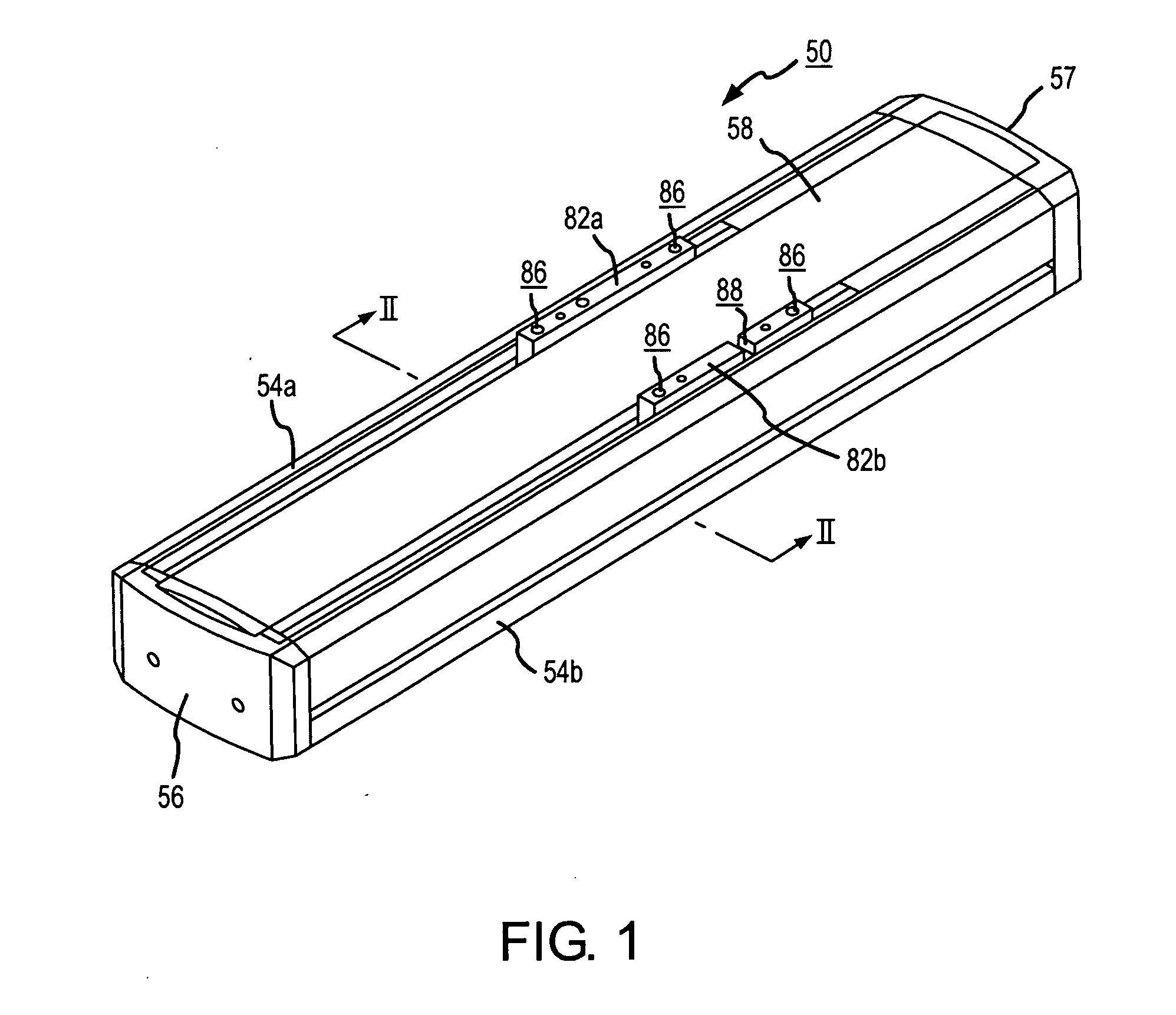
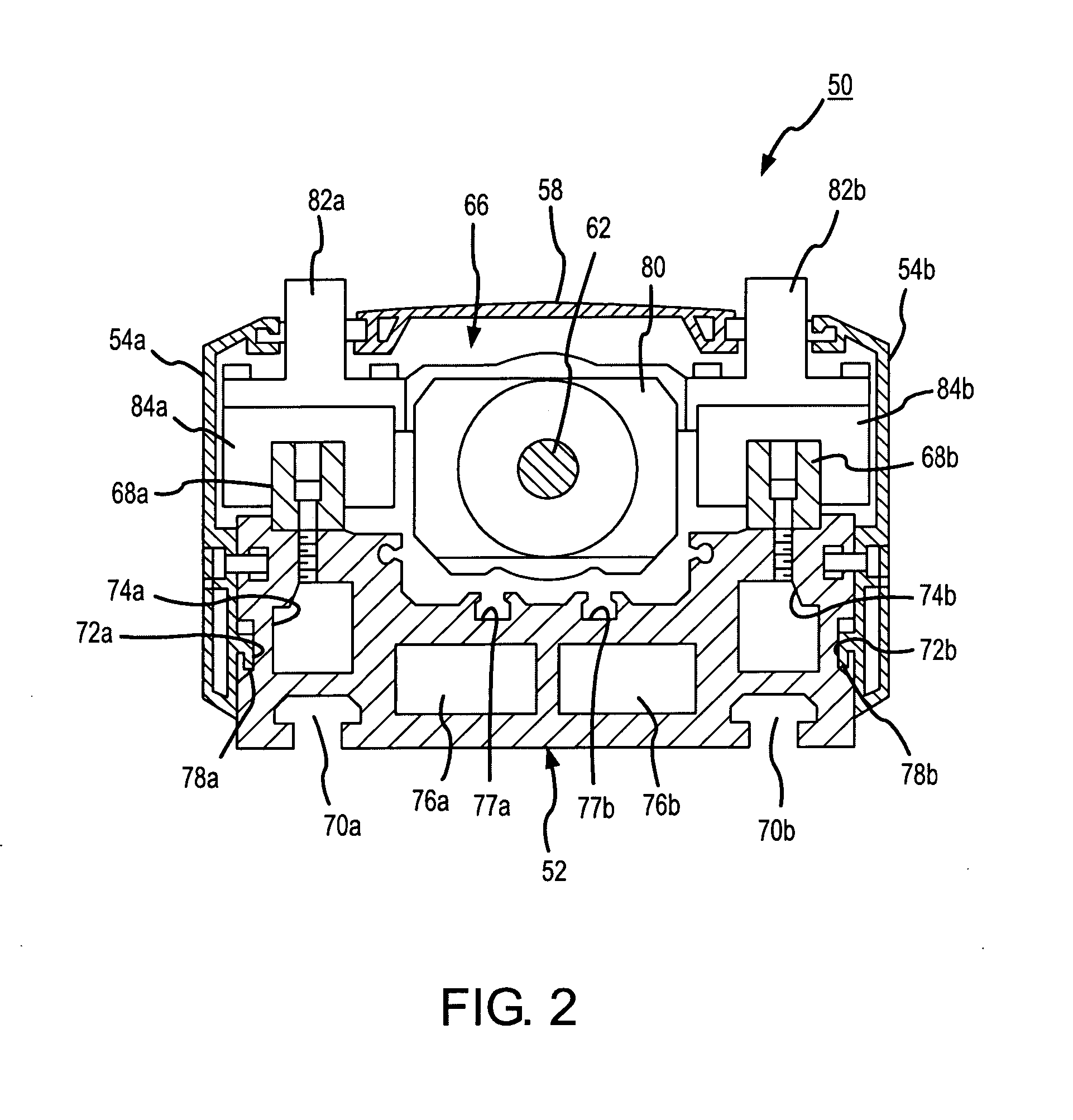
[0031] A known type of electric linear actuator, to which the principles of the present invention are applied, is shown in FIGS. 1 through 3.

[0032] The electric actuator, generally denoted at 50 in FIGS. 1 through 3, comprises an elongate frame 52 as a base, a pair of elongate side covers 54a, 54b mounted respectively on transversely opposite sides of the frame 52, a pair of end covers 56, 57 mounted respectively on longitudinally opposite ends of the frame 52, and an elongate top cover 58 engaging upper surfaces of the side covers 54a, 54b.

[0033] On the frame 52, there are mounted a drive mechanism 60 fixed to one end of the frame 52 and supporting one end of a ball screw 62, a bearing block 64 fixed to the other end of the frame 52 and supporting the other end of the ball screw 62, and a table mechanism 66 linearly displaceable between the drive mechanism 60 and the bearing block 64 by the ball screw 62 upon rotation thereof. A pair of transversely spaced guide members 68a, 68b ...


PUM


Abstract

A stepping motor is driven in both closed-loop and open-loop modes while initiating microstepping after a predetermined threshold velocity has been reached. A feedback device such as an encoder is mounted on the stepping motor shaft and the encoder keeps track of the mechanical position of the rotor. Based on feedback from the encoder, stator phases are activated to maintain a 90° phase advance and produce maximum torque. A lead angle compensation technique is used to advance the motor lead angle, to allow for the excitation currents to reach maximum even at higher speeds. The stepping motor controller employs this strategy in order to produce maximum torque across a wide range of motor speeds and actuator motions.

Description

FIELD OF THE INVENTION [0001] The present invention relates to a control system and method for controlling a stepping motor having plural phase windings. BACKGROUND OF THE INVENTION [0002] Stepping motors, which are typically driven without a feedback device, have been used in open-loop positioning systems for many years. However, such open-loop stepping systems frequently exhibit undesirable behaviors such as stepping resonance and loss of synchronization. [0003] Nevertheless, stepping motors are low in cost and are used extensively and at high volume in various industries. Further, because they have many poles operated using plural phase windings, stepping motors produce high torque at a given motor winding current. Such characteristics are particularly suited for a variable-speed positioning controller, and allow the need for auxiliary gear reduction mechanisms, for mechanical force-speed conversion, to be eliminated or at least minimized. [0004] Prior techniques using a closed-l...

Claims


Application Information

Patent Timeline
IPC IPC(8): G05B19/40
CPCG05B19/40G05B2219/42122G05B2219/43083H02P8/005H02P8/08H02P8/22H02P23/20
Inventor TAKEBAYASHI, TAKASHICHO, DAVID S.TOMOV, PAVELGOKHALE, DIPEN
Owner SMC CORP OF AMERICA
Why Eureka
Try Eureka