Analogue self-calibration method and apparatus for low noise, fast and wide-locking range phase locked loop

a phase locking loop, low noise technology, applied in the direction of electrical equipment, pulse automatic control, resonance circuit tuning, etc., can solve the problem of high parasitic capacitance, low noise performance, and increased complexity of extra blocks proportionally to the needed output frequency accuracy, so as to improve noise performance, low vco gain, and the effect of not using

Inactive Publication Date: 2007-02-22
MARVELL ASIA PTE LTD
View PDF10 Cites 22 Cited by
  • Summary
  • Abstract
  • Description
  • Claims
  • Application Information

AI Technical Summary

Benefits of technology

[0011] The aim of the present invention is to provide a method and apparatus for a fast and automatic setting of the phase locked loop (PLL) output frequency over a wide tuning r...

Problems solved by technology

The VCO control path is in general affected by several noise sources that include: charge pump noise, filter noise and ripple due to mismatching between the charge pump up and down currents.
The complexity of those extra blocks increases proportionally to the needed accuracy of the output frequency.
Therefore, a very high frequency overlap is required to compensate these errors, leading to a higher gain of the VCO, a lower total tuning range, and a higher parasitic capacitance.
This is why digital calibration can result in prolonged design cycles with...

Method used


Image

  • Analogue self-calibration method and apparatus for low noise, fast and wide-locking range phase locked loop
  • Analogue self-calibration method and apparatus for low noise, fast and wide-locking range phase locked loop
  • Analogue self-calibration method and apparatus for low noise, fast and wide-locking range phase locked loop

Examples


Embodiment Construction

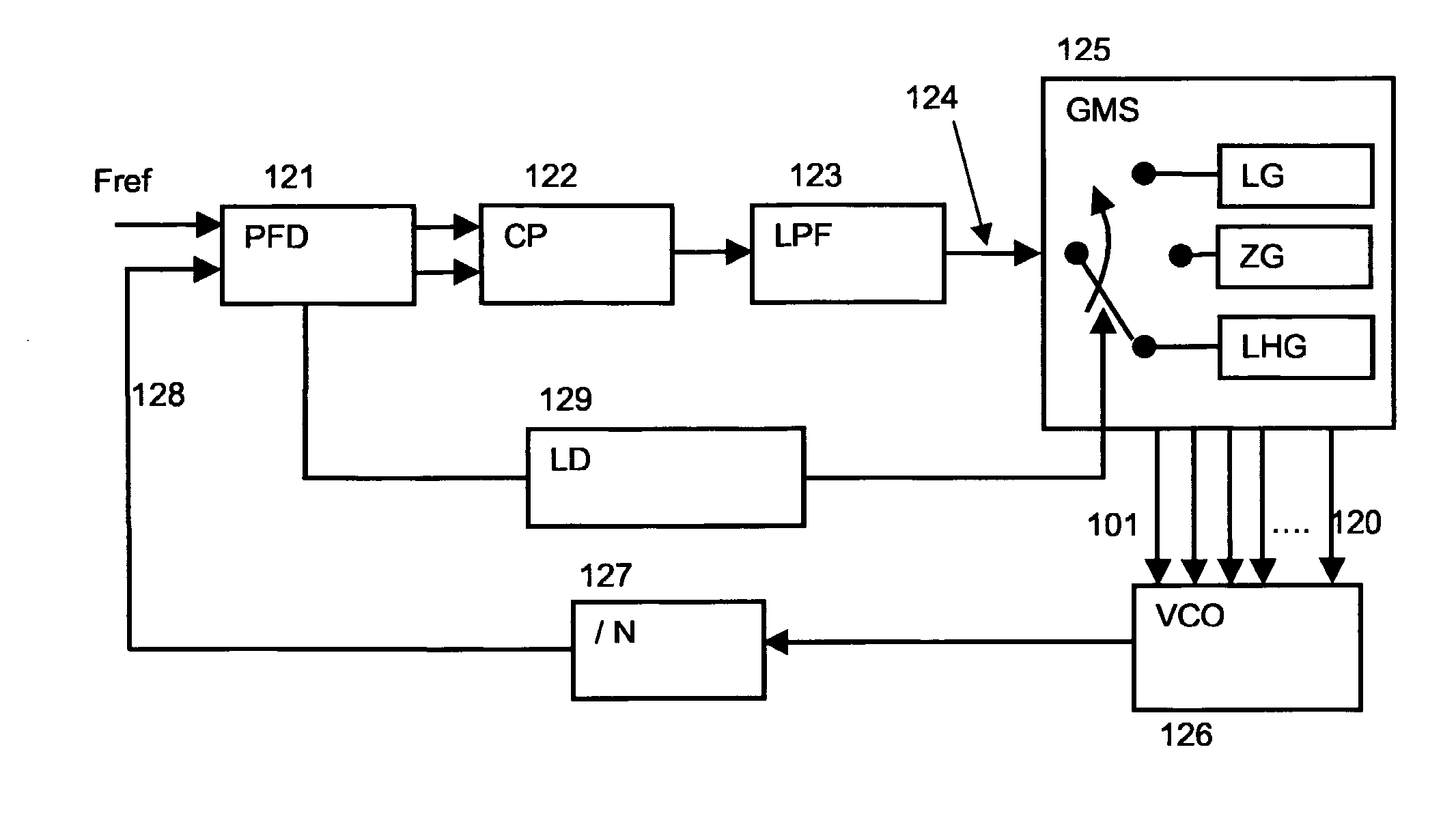
[0033]FIG. 1 is a functional block diagram of the charge pump phase locked loop (PLL) system in accordance with the present invention. The PLL circuit, generally designed 100, includes a Phase / Frequency detector (PFD) 121 to compares the phase and the frequency of the reference signal (Fref) to the phase and the frequency of the feedback signal 128, and generates an error signal. The error signal is either an up signal or a down signal depending on the sign of the detected error.

[0034] Charge pump CP 122 generates an amount of charge equivalent to the error signal provided by the Phase / Frequency detector PFD 121. Depending upon the polarity of the signal (up or down), the charge is either added to or subtracted from a capacitor in the Low Pass Filter (LPF) 123. Accordingly, the low pass loop filter 123 generates a voltage 124 that will be applied to the input of the Gain-Mode Switcher 125 (GMS).

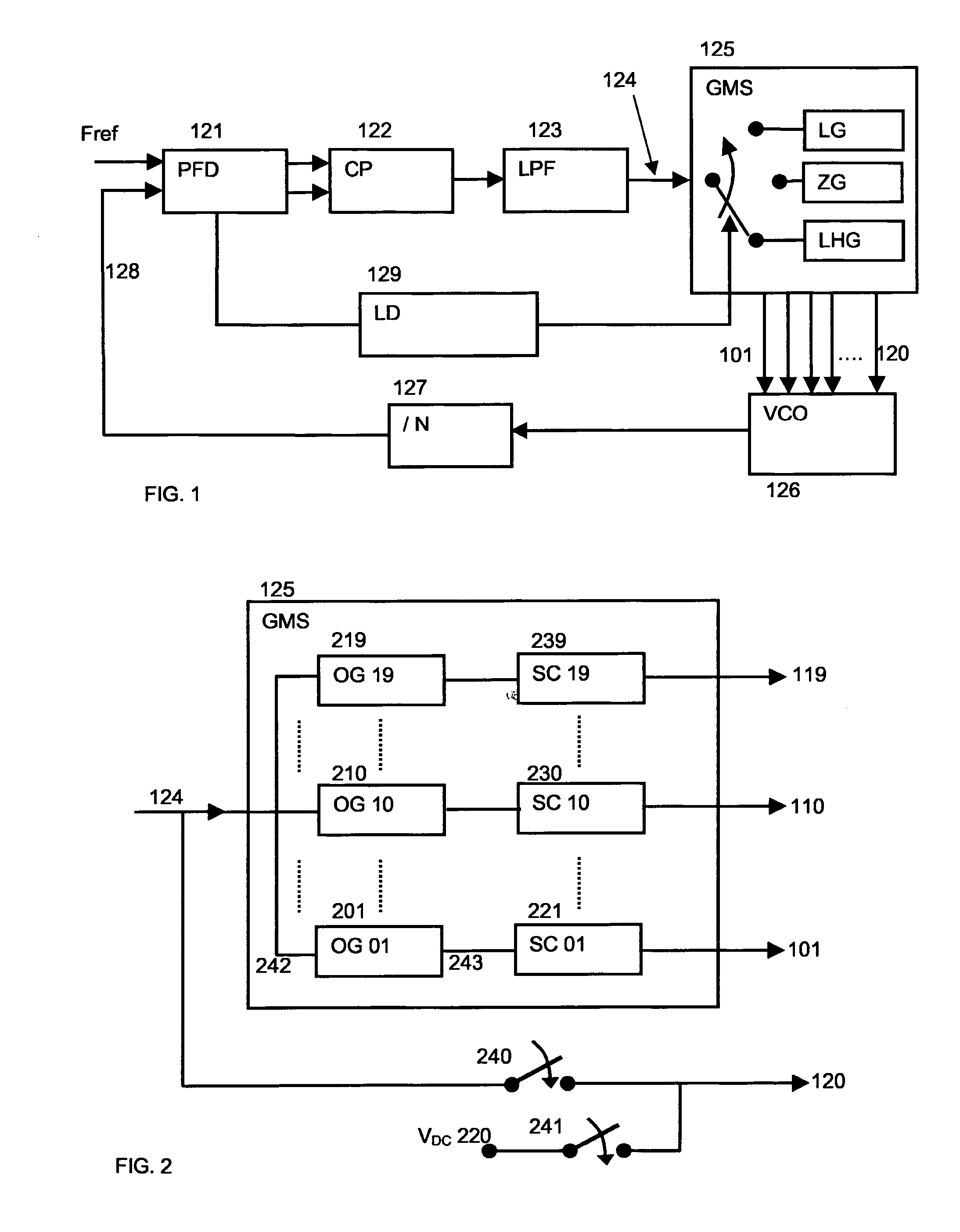
[0035] The Gain-Mode Switcher (GMS) 125 is the block of the PLL 100 that enables to...


PUM


Abstract

A method and apparatus for a fast and automatic setting of the phase locked loop (PLL) output frequency that significantly improves linearity, locking range as well as spectrum purity, jitter and phase noise performances is disclosed. In one embodiment, a PLL frequency synthesizer is disclosed having a reconfigurable voltage controlled oscillator VCO with three modes of operation: a Linear-High-gain, Zero-gain, and Low-gain mode. During a first tuning operation, the VCO work in a linear high gain mode, enabling a totally analogue self-calibration of the PLL over a wide frequency tuning range and with a fast settling time. During this operation the control voltage at the input of the VCO is varied by the PLL until the appropriate output frequency is found. A method for providing a linear variation of the frequency over all the voltage tuning range during this mode is disclosed. When the loop is locked, the VCO is automatically switched to the Zero-gain mode while keeping its frequency unchanged. Its sensitivity to the noise in the control path is then practically eliminated and its phase noise performances significantly improved. If the frequency error and phase noise are sufficiently small for the considered application the tuning is stopped. If the error and phase noise are not sufficiently small the VCO is switched again to Low-gain mode and fine-tuning adjustment of the output frequency is achieved.

Description

PRIORITY STATEMENT [0001] This application is the national phase under 35 U.S.C. § 371 of PCT International Application No. PCT / EP2005 / 050484 which has an International filing date of Feb. 4, 2005, which designated the United States of America and which claims priority on European Patent Application number 04100600.8 filed Feb. 13, 2004. BACKGROUND OF THE INVENTION [0002] 1. Field of the Invention [0003] The present invention relates to a Phase Locked Loop (PLL) circuit having a variable output frequency. More particularly, the present invention consists of an improved method for a fast and automatic setting of the output frequency of PLL synthesizers that overcomes the classical problems associated with prior implementation, concerning: linearity, locking range limitation, settling time, jitter, phase noise, and spectral purity deterioration. [0004] 2. Description of the Prior Art [0005] A Phase-Locked Loop (PLL) synthesizer is a circuit used to generate a periodic signal with a pr...

Claims


Application Information

Patent Timeline
IPC IPC(8): H03L7/00H03L7/093H03L7/095H03L7/099H03L7/10H03L7/107
CPCH03J2200/10H03L7/095H03L2207/05H03L7/10H03L7/107H03L7/099H03L7/1075
Inventor KOUKAB, ADILDECLERCO, MICHEL
Owner MARVELL ASIA PTE LTD
Why Eureka
Try Eureka