
Method and apparatus for shielding correction pixels from spurious charges in an imager

a technology of image sensor and shielding pixel, applied in the field of shielding pixel from spurious charges in image sensors, can solve the problems of row banding and distortion of the resultant image, inaccurate dark correction levels, and inaccuracy of dark correction levels

Active Publication Date: 2007-02-22
APTINA IMAGING CORP
View PDF16 Cites 18 Cited by
  • Summary
  • Abstract
  • Description
  • Claims
  • Application Information

AI Technical Summary

Benefits of technology

[0013] Exemplary embodiments of the invention provide a barrier for isolating the dark correction pixels of an image sensor. The barrier comprises a charge absorbing region in a substrate electrically connected to a voltage source terminal. The charge absorbing region is completely surrounds the dark correction region of a pixel array. The charge absorbing region absorbs carriers generated by lateral diffusion, near-infrared and infrared light reflected from the bottom of the silicon substrate, and charges from other sources that may diffuse into dark correction pixels. This absorbing region prevents carriers from being absorbed into the dark correction pixel cells and causing row banding and other image distorting effects.

Problems solved by technology

These sources, and others, cause inaccurate dark correction levels.
This causes inaccurate dark correction levels, resulting in row banding and distortion of the resultant image.

Method used


Image

  • Method and apparatus for shielding correction pixels from spurious charges in an imager
  • Method and apparatus for shielding correction pixels from spurious charges in an imager
  • Method and apparatus for shielding correction pixels from spurious charges in an imager

Examples


Embodiment Construction

[0027] In the following detailed description, reference is made to the accompanying drawings, which form a part hereof and illustrate specific embodiments in which the invention may be practiced. In the drawings, like reference numerals describe substantially similar components throughout the several views. These embodiments are described in sufficient detail to enable those skilled in the art to practice the invention, and it is to be understood that other embodiments may be utilized, and that structural, logical and electrical changes may be made without departing from the spirit and scope of the present invention.

[0028] The terms “wafer” and “substrate” are to be understood as including silicon, silicon-on-insulator (SOI), or silicon-on-sapphire (SOS) technology, doped and undoped semiconductors, epitaxial layers of silicon supported by a base semiconductor foundation, and other semiconductor structures. Furthermore, when reference is made to a “wafer” or “substrate” in the foll...


PUM


Abstract

A barrier for isolating the dark correction pixels from spurious charges within an image sensor. The barrier comprises a charge absorbing region in a substrate electrically connected to a voltage source terminal. The charge absorbing region completely surrounds the dark correction region of a pixel array. The charge absorbing region absorbs carriers generated by lateral diffusion, near-infrared and infrared light reflected from the bottom of the silicon substrate, and other sources. This absorbing region prevents carriers from being absorbed into the dark correction pixel cells and causing image correction distorting effects.

Description

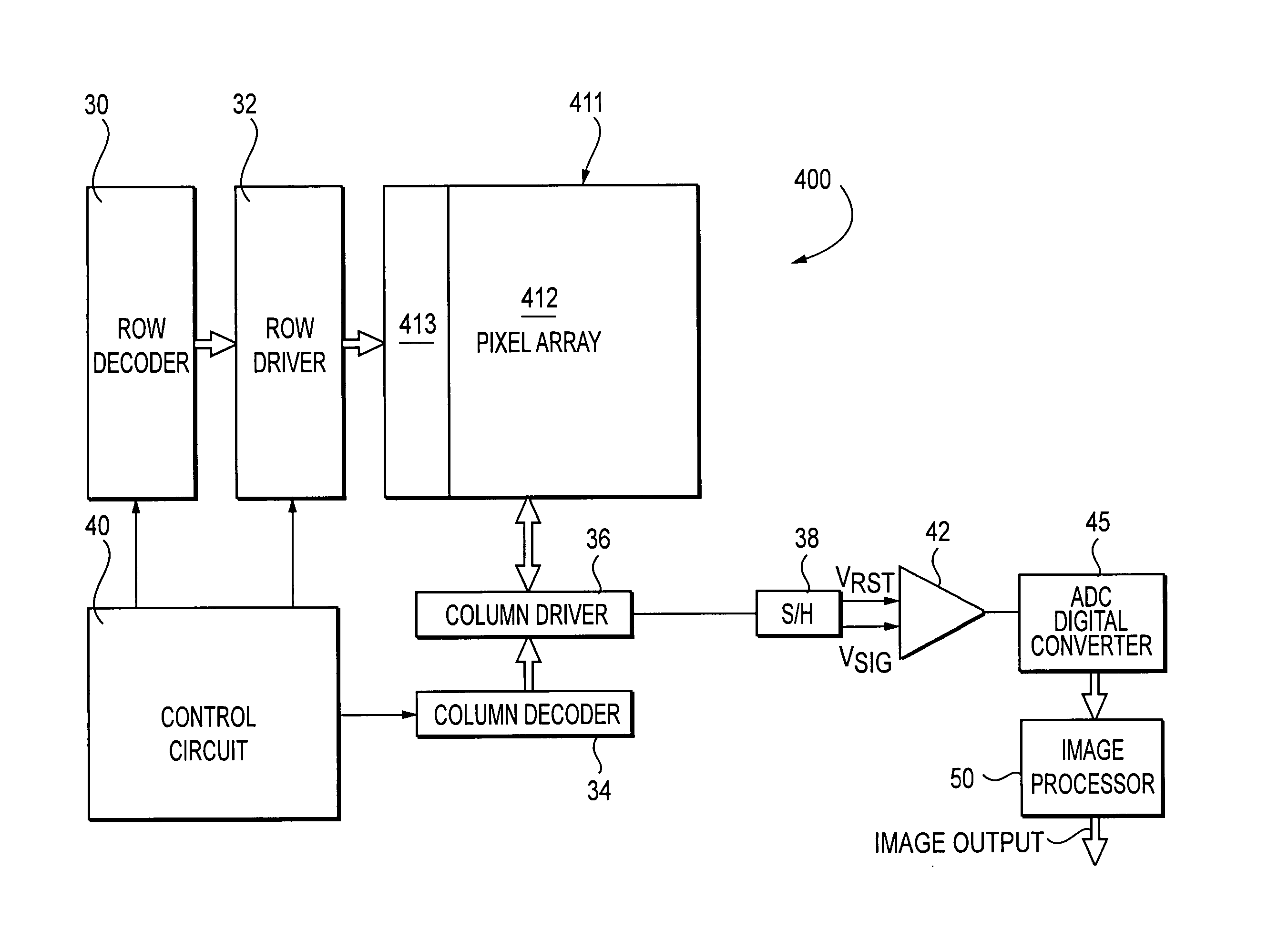
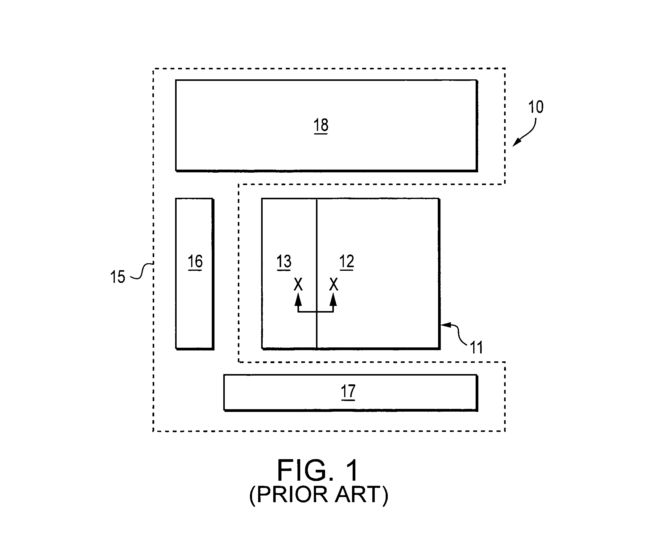
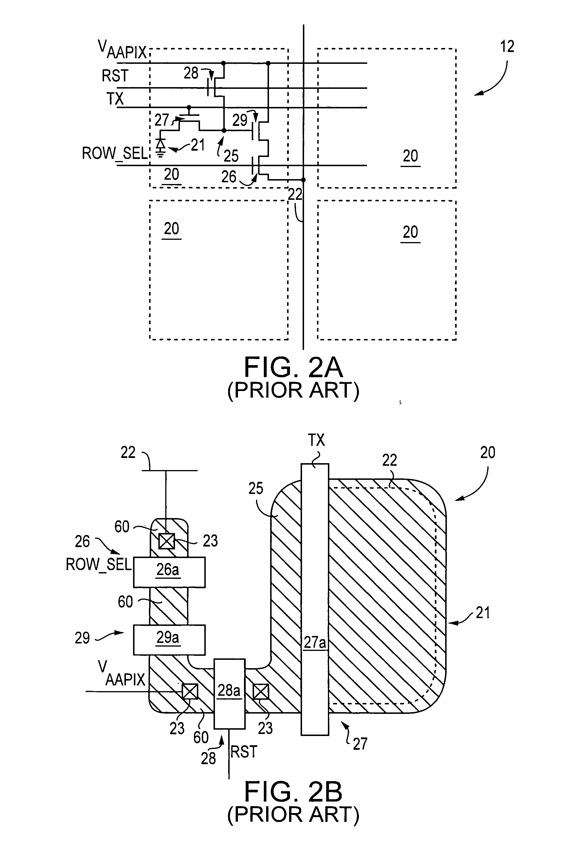
FIELD OF THE INVENTION [0001] The present invention relates to the field of semiconductor devices, and particularly to improved charge isolation techniques for image sensors. BACKGROUND OF THE INVENTION [0002] An image sensor generally includes an array of pixel cells. Each pixel cell includes a photo-conversion device for converting light incident on the array into electrical signals. An image sensor also typically includes peripheral circuitry for controlling devices of the array and for converting the electrical signals into a digital image. [0003]FIG. 1 is a top plan view block diagram of a portion of a typical CMOS image sensor 10. The image sensor 10 includes an array 11 of pixel cells arranged in columns and rows (not shown). The array 11 includes pixel cells 20 (FIG. 2A) in an active array region 12 and pixel cells 20′ (FIG. 3) in a dark correction region 13 that are used for noise or dark correction. FIG. 2A is a schematic diagram of typical pixel cells 20 and FIG. 2B is a ...

Claims


Application Information

Patent Timeline
Patent Type & Authority Applications(United States)
IPC IPC(8): H04N1/46H04N25/00
CPCH01L27/1463H01L27/14654H01L27/146
Inventor CHINNAVEERAPPAN, KALAIRAJAHONG, SUNGKUKLEE, JI SOOHONG, SUNGKWON C.
Owner APTINA IMAGING CORP
Learn More