Dc-dc converter

a converter and converter technology, applied in the direction of electric variable regulation, process and machine control, instruments, etc., can solve the problems of insufficient performance and increase in switching loss, and achieve the effects of enhancing switching efficiency, suppressing switching loss, and simple structur

Inactive Publication Date: 2007-02-22
HONDA MOTOR CO LTD
View PDF5 Cites 26 Cited by
  • Summary
  • Abstract
  • Description
  • Claims
  • Application Information

AI Technical Summary

Benefits of technology

[0018] According to a first feature of the present invention, a driving frequency for the switching means and a resonant frequency of the resonant circuit can always be kept to the same as each other by using a simple structure, so that it is possible to suppress switching loss and enhance switching efficiency. Further, even if element constants of circuit elements of the resonant circuit fluctuate through a stage of manufacturing or change as time passes by or due to an ambient temperature after being incorporated into a DC-DC converter, the driving frequency for the switching means is automatically adjusted to agree with the resonant frequency of the resonant circuit, thereby facilitating designing the circuit and the elements.
[0019] According to a second feature of the present invention, resonant frequency detecting means and the driving means can share a common voltage reference line and, therefore, need not be insulated from each other.
[0020] According to a third feature of the present invention, low-voltage side switching means and high-voltage side switching means are operated at the same driving timing to enable conversion that accommodate power bi-directionally, in which case switching loss can be suppressed with a simple structure. Further, a current waveform due to switching of the switching means is shaped into a sine wave through an LC resonant circuit and the driving frequency for the switching means is automatically adjusted to agree with the resonant frequency of the LC resonant circuit, so that a turn-OFF timing of a switching element can be kept extremely close to a zero-crossing point of a resonant current. It is thus possible to suppress switching loss greatly.
[0021] According to a fourth feature of the present invention, the high-voltage side where the LC resonant circuit is provided has a small value of a current flowing through it, so that loss through the LC resonant circuit can be suppressed.
[0022] According to a fifth feature of the present invention, the switching means and a rectifying element on each of the high-voltage and low-voltage sides make up a so-called bridge-type single-phase inverter, so that a structure of a transformer can be simplified. Further, conversion efficiency can be enhanced because it is unnecessary to prolong a short-circuit-preventing dead time for the switching element owing to a lag in transmission through the transformer or reduce a driving time for the switching element.

Problems solved by technology

As may be clear from these figures, if a shift develops between the turn-ON / -OFF frequency of the switching means 2 and the resonant frequency of the resonant circuit 3, the switching means will not be turned ON or OFF near a zero-crossing point of a resonant current, so that switching loss increases, thus resulting in sufficient performance not being obtained.

Method used


Image

  • Dc-dc converter
  • Dc-dc converter
  • Dc-dc converter

Examples


Embodiment Construction

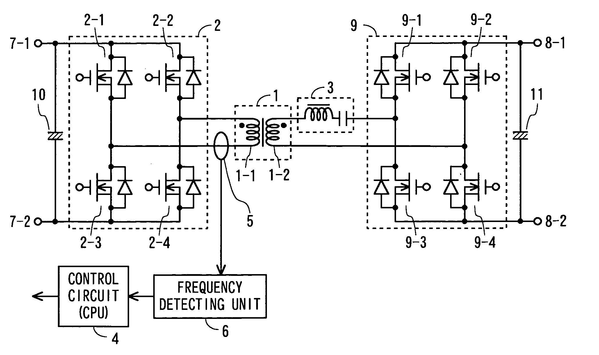
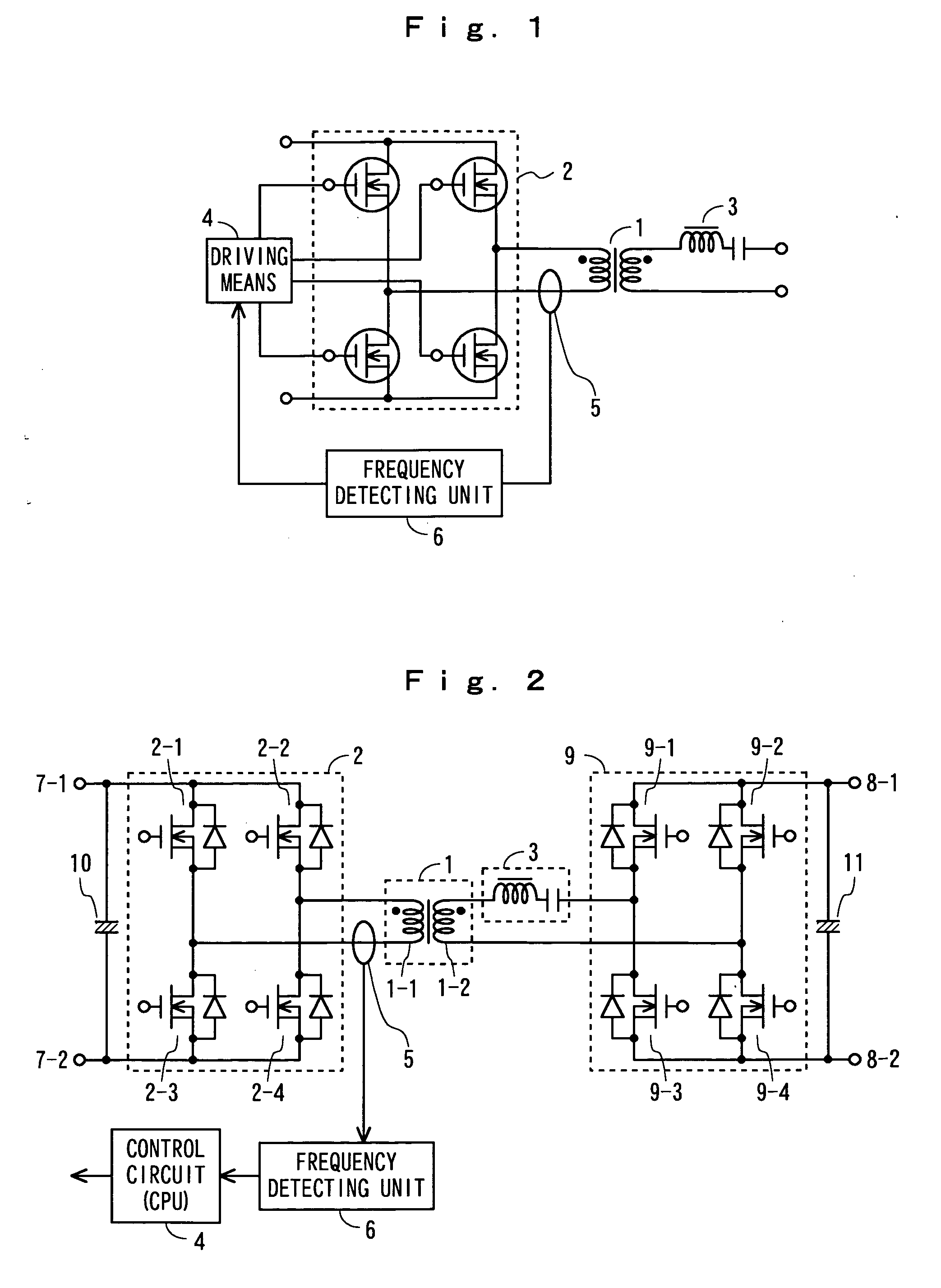
[0029] The present invention will be described below with reference to drawings. FIG. 1 is a circuit diagram showing a principle of a DC-DC converter related to the present invention. In the following, the same components as those of FIG. 4 or similar components are indicated by the same reference numerals. FIG. 1 is different from FIG. 4 in that resonant current frequency detecting means which detects a frequency of a resonant current due to operations of a resonant circuit 3 is provided so that a frequency detected by this means may be fed back to driving means 4. The resonant current frequency detecting means is composed of a resonant current detecting current transformer 5 arranged on a line through which, for example, a resonant current on the primary side of a transformer 1 flows and a frequency detecting unit 6 for detecting a frequency of a resonant current detected by this transformer 5.

[0030] Next, operations of FIG. 1 are described. First, the driving means 4 turns the s...


PUM


Abstract

To provide a DC-DC converter capable of suppressing switching loss with a simple structure, and capable of enhancing converting efficiency.
An LC resonant circuit 3 is inserted on a secondary side of a transformer 1. If switching means 2 is turned ON or OFF by driving means 4, output can be obtained on the secondary side through the transformer 1. A resonant current frequency detecting means comprises a current detecting current transformer 5 and a frequency detecting unit 6. The resonant current frequency detecting means detects resonant current frequency caused by operation of the LC resonant circuit 3. This frequency is fed back to the driving means. As a result, the driving means 4 turns the switching means 2 ON or OFF at a frequency corresponding to the resonant frequency of the LC resonant circuit 3.

Description

TECHNICAL FIELD [0001] The present invention relates to a DC-DC converter, particularly to a DC-DC converter that can suppress switching loss and enhance converting efficiency. BACKGROUND ART [0002] A current-resonant type DC-DC converter is equipped with a resonant circuit connected in series with switching means and turns ON and OFF the switching means at a resonant frequency of the resonant circuit. FIG. 4 shows a principle of the DC-DC converter. On the primary side of a transformer 1, switching means 2 is provided which has a bridge configuration composed of, for example, four switching elements, and on the secondary side thereof, a resonant circuit 3 is provided. The resonant circuit 3 is composed of a resonating choke (reactor) and a resonating capacitor. It is to be noted that on the secondary side, rectifying means and smoothing means, which are not shown though, are further provided. [0003] If the switching means 2 is turned ON or OFF by driving means 4 at a resonant frequ...

Claims


Application Information

Patent Timeline
Patent Type & Authority Applications(United States)
IPC IPC(8): H02M3/335H02M3/155H02M1/10
CPCH02M1/10H02M3/33592H02M7/5387Y02B70/1433Y02B70/1441Y02B70/1475Y02B70/10H02M3/28
Inventor EGUCHI, HIROYUKISHIMIZU, MOTOHIRO
Owner HONDA MOTOR CO LTD
Why Eureka
Try Eureka