Bone-conduction hearing-aid transducer having improved frequency response

a transducer and bone conduction technology, applied in the field of assisting in the perception of sound, can solve the problems of inability to use beyond 4 khz, inability to accurately detect the sound, and inability to conduct air conducted noise, etc., and achieve the effect of eliminating soldering wires

Inactive Publication Date: 2007-02-22
FACE INT
View PDF5 Cites 214 Cited by
  • Summary
  • Abstract
  • Description
  • Claims
  • Application Information

AI Technical Summary

Benefits of technology

[0052] The specific design of the tap also bypasses the use of wires to connect the actuator. The use of wires on the surface in contact with the patient's head will be a source of discomfort and will partially disrupt the mechanical contact between the actuator tip and the head. In order to solve this issue, two taps with completely flat and thin metallic extensions are designed that can be extended out of the transducer up t...

Problems solved by technology

If the noise intensity level is too high, the air conducted noise will overshadow the bone conducted signal giving rise to inaccuracies in hearing level experiments.
Conventional actuators such as the B-71, st...

Method used


Image

  • Bone-conduction hearing-aid transducer having improved frequency response
  • Bone-conduction hearing-aid transducer having improved frequency response
  • Bone-conduction hearing-aid transducer having improved frequency response

Examples


first embodiment

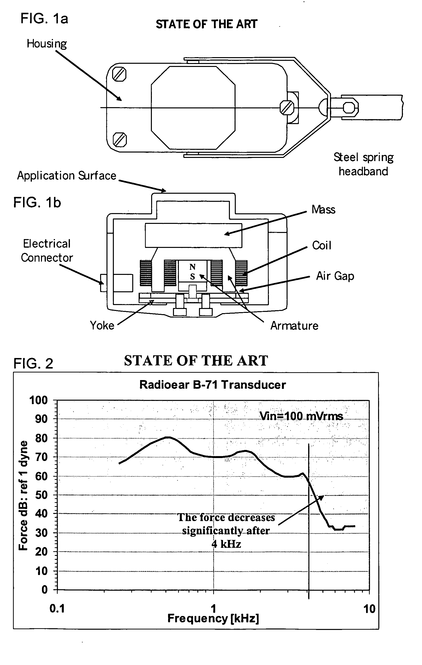
[0109] Housing 1 (31 g brass housing). FIG. 11 show the force variation with frequency at input voltage levels of 2 and 10 Vrms respectively. 8C6S_epoxy signifies that the Thunder 1 was attached to the brass housing 100 at four diametrically opposite points (90° apart) with epoxy 80. As expected, the increase in the applied voltage shows a distinctive increase in the force level at each frequency. The actuators 12 show a well-defined response in the range of 250 Hz to over 8 kHz (only plotted up to 8 kHz). The force level at 100 Hz was low and the reading was not accurate at that frequency point. The response of the Radioear B-71 at 0.1 Vrms is also shown in each of the figures to emphasize on the dramatic performance improvement with Thunder technology.

[0110] For all the voltage levels, it is seen that the various bone vibration transducers 1 made with different Thunder actuators 12 thickness show very similar response. However, the transducer TH-8C6S shows a slightly better perfo...

second embodiment

[0111] Housing 2 (51 g brass housing). FIG. 13 shows the force vs. frequency behavior of the Thunder Bone Conduction transducers 1 with 51 g brass housing at 2 and 10 Vrms input voltage level. The response is very similar to the ones with 31 g housing except that the low frequency response is improved. However, the dip in the range 5-8 kKz is larger which is not desirable. Further, the overall fluctuation in the force response is seen to be the highest in the TH-8C6S transducer which was considered to be best when used with 31 g mass.

[0112] Table 5 shows the performance of TH-8C6S Bone Conduction transducer 1 when used with 51 g brass housing 100. The ANSI S3.43 (1992) specifications and the values desired by HCRI are also depicted in the table. FIG. 9 shows the different force response curves for the TH-8C6S transducer for the applied voltage levels.

TABLE 5TH-8C6S Bone Conduction transducer with 51 g brass housing.Force (dB: ref 1 dyne)Measured at Face at voltage inputsFrequency...

third embodiment

[0113] Housing 3 (21 g aluminum housing). The test results with the two brass housings showed that increasing the mass of the system improved the frequency response of the transducer in the lower frequency range as a second order system would do. The interest then shifted towards making the system comparable in mass to the Radioear B-71 and see if there would be a drastic loss of performance in the lower frequency region. FIG. 15 shows the performance of a selected few Thunders when used with the 21 g aluminum housing. The Radioear B-71 performance at an input voltage of 0.1 Vrms included in the plots.

[0114]FIG. 16 shows the frequency response of TH-10C10S Bone Conduction tranducer at 2, 10 and 20 Vrms with the 21 g aluminum housing obtained from the data of Table 6.

TABLE 6TH-10C10S Bone Conduction transducer with 21 g aluminum housing.Force (dB: ref 1 dyne)Measured at Face at voltage inputsFrequencyANSI S3.43ofHCRI(Hz)(1992)2 Vrms10 Vrms20 VrmsSpecs.100—35.044.251.0—25072.051.16...


PUM

PropertyMeasurementUnit
Frequencyaaaaaaaaaa
Frequencyaaaaaaaaaa
Frequencyaaaaaaaaaa

Abstract

A hearing-aid device and a method for transmitting sound through bone conduction are disclosed. The hearing-aid device comprises a piezoelectric-type actuator, housing and connector. The piezoelectric actuator is preferably a circular flextensional-type actuator mounted along its peripheral edge in a specifically designed circular structure of the housing. During operation, the bone-conduction transducer is placed against the mastoid area behind the ear of the patient. When the device is energized with an alternating electrical voltage, it flexes back and forth like a circular membrane sustained along its periphery and thus, vibrates as a consequence of the inverse piezoelectric effect. Due to the specific and unique designs proposed, these vibrations are directly transferred trough the human skin to the bone structure (the skull) and provide a means for the sound to be transmitted for patients with hearing malfunctions. The housing acts as a holder for the actuators, as a pre-stress application platform, and as a mass which tailors the frequency spectrum of the device. The apparatus exhibits a performance with a very flat response in the frequency spectrum 200 Hz to 10 kHz, which is a greater spectrum range than any other prior art devices disclosed for bone-conduction transduction which are typically limited to less than 4 kHz.

Description

[0001] This application claims the benefit of priority under 35 U.S.C. 119(e) from U.S. Provisional Application 60 / 697,510 filed on Jul. 7, 2005.BACKGROUND OF THE INVENTION [0002] 1. Field of the Invention [0003] The present invention relates to the field of devices and methods for assisting in the perception of sound for the hearing impaired and more specifically to a transducer type for listening to sounds by an abutment to the head for the transmission of transducer vibration to the skull structure. More particularly, the present invention relates to a bone conduction hearing aid having the vibrator element directly in contact with the skin surface of the patient's head. [0004] 2. Description of the Prior Art [0005] The human auditory system, consisting of the ears and associated brain structures, possesses remarkable signal processing capabilities. We hear sounds from those that are barely detectable to those that reach the threshold of pain—a difference of about 130 decibels or...

Claims


Application Information

Patent Timeline
IPC IPC(8): H04R25/00
CPCH04R1/1066H04R1/1091H04R17/00H04R25/604H04R29/001H04R2460/13Y10T29/49572
Inventor CARAZO, ALFREDO VAZQUEZMALLA, AAYUSH
Owner FACE INT
Why Eureka
Try Eureka