Method and apparatus for cleaning slurry depositions from a water carrier

a technology of slurry and water carrier, which is applied in the direction of cleaning with liquids, manufacturing tools, lapping machines, etc., can solve the problems of potential wafer yield loss, wafer scratches and failing particle counts, and/or other components in the slurry becoming a contamination issue,

Inactive Publication Date: 2007-02-22
BELL SEMICON LLC
View PDF7 Cites 0 Cited by
  • Summary
  • Abstract
  • Description
  • Claims
  • Application Information

AI Technical Summary

Benefits of technology

[0001] Conventional chemical / mechanical polishing (CMP) is used to create smooth topographies of the various layers of a semiconductor integrated circuit wafer during semiconductor device manufacture. The CMP process involves holding and rotating, using a wafer carrier, semiconductor wafer against a rotating polishing pad. The wafer carrier is typically a plate-like structure having a diameter slightly larger than the semiconductor wafer. The carrier is attached to a positioning device through a gimbal on its back side surface that allows the carrier to be spun and to pivot on the gimbal. The polishing pad, which is conventionally an open-celled, polyurethane pad affixed to a polishing platen, is wetted by a chemical slurry, under controlled chemical, pressure, and temperature conditions. The chemical slurry contains selected chemicals which etch or oxidize selected surfaces of the wafer during CMP in preparation for their mechanical removal. The slurry also contains a polishing agent, such as alumina or silica that is used as the abrasive material for the physical removal of the etched / oxidized material. The combination of chemical and mechanical removal of material during polishing results in superior planarization of the polished surface. In this process it is important to remove a sufficient amount of material to provide a smooth surface, without removing an excessive amount of underlying materials at each level of the manufacturing process to insure uniform and accurate formation of the semiconductor device at all subsequent levels. Accurate material removal is particularly important in today's sub-quarter micron technologies where it is critical to minimize thickness variation because the metal lines are thinner.

Problems solved by technology

Further, when this splashed slurry dries, the silica and / or other components in the slurry become a contamination issue.
Dried silica particles falling on the polishing pad is one of the causes of wafer scratches and failing particle counts when process checking a tool.
The scratching results in potential wafer yield losses.
The failing particle counts during process checking results in diminished tool availability since the tool must be taken out of production and cleaned.

Method used


Image

  • Method and apparatus for cleaning slurry depositions from a water carrier
  • Method and apparatus for cleaning slurry depositions from a water carrier

Examples


Embodiment Construction

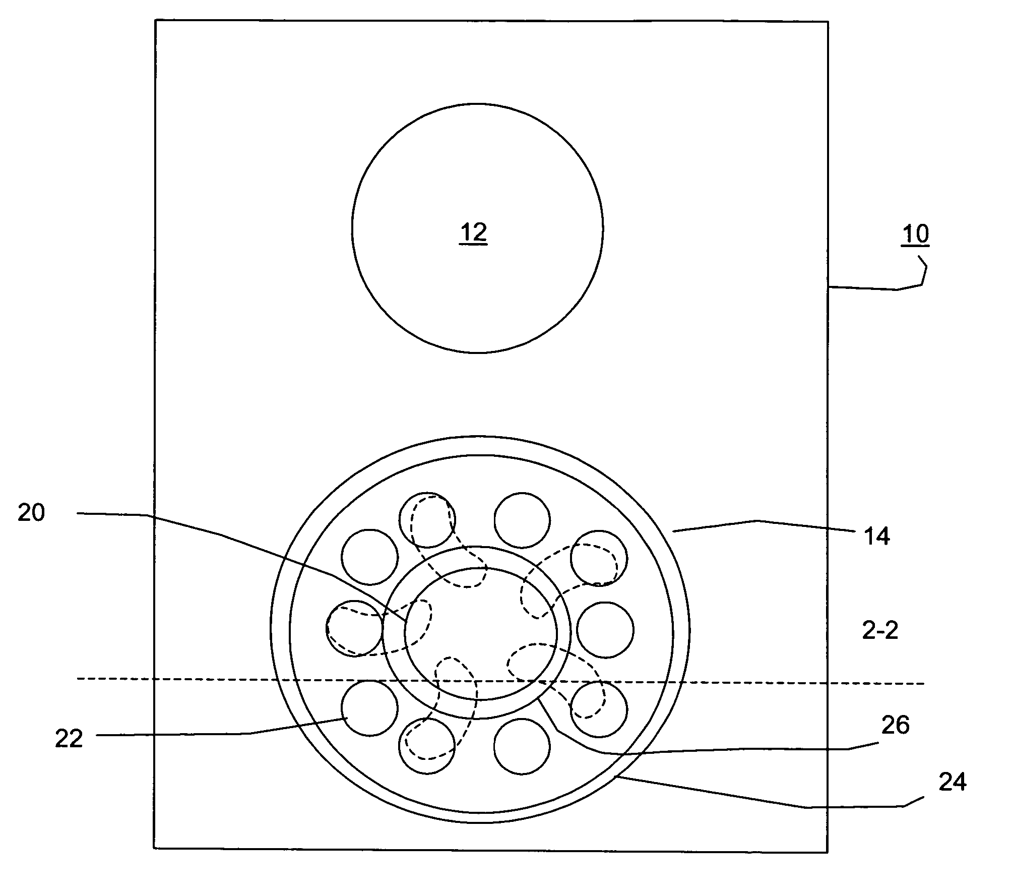
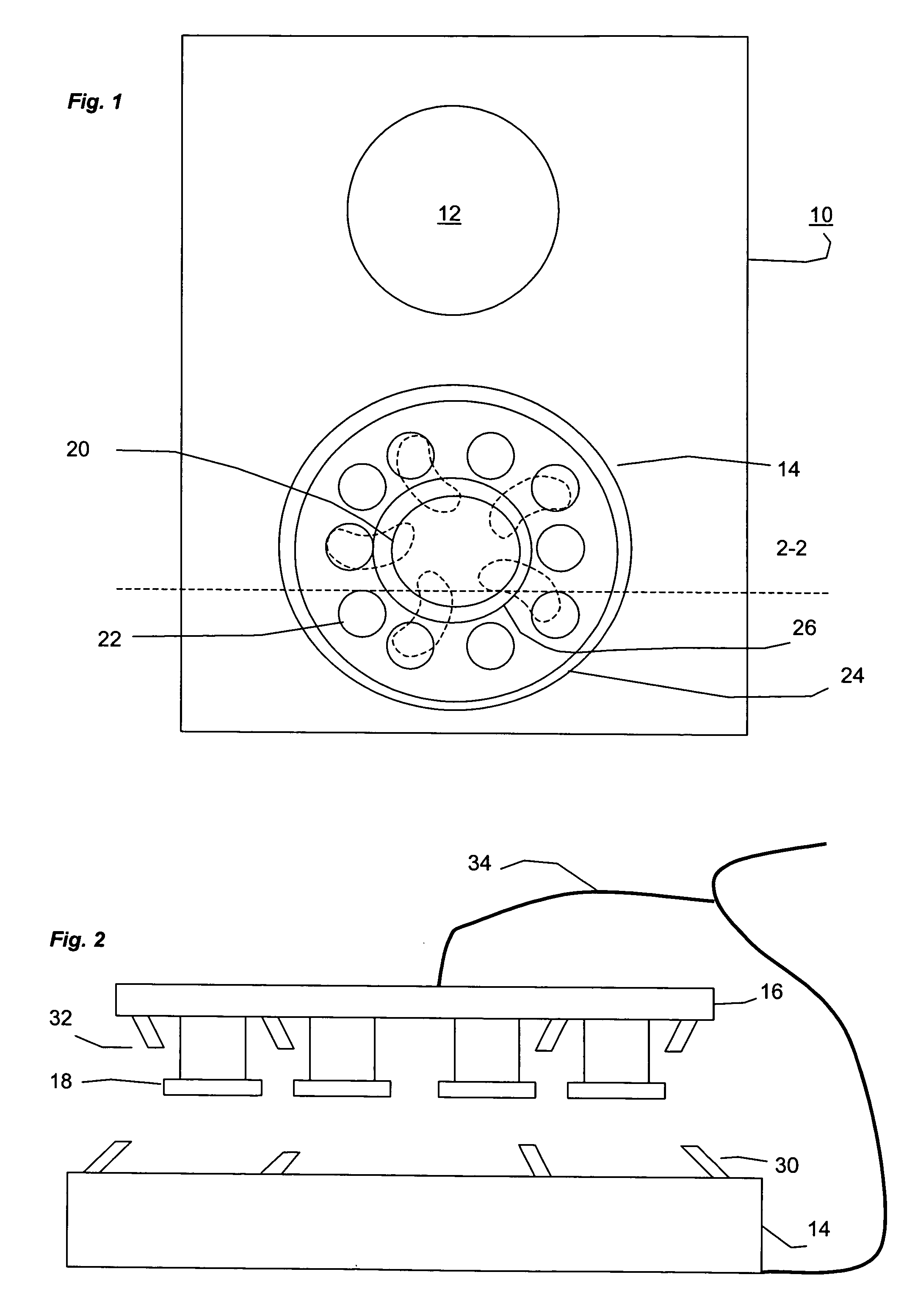
[0007] Referring now to FIGS. 1 and 2, FIG. 1 being highly simplified top plan view and FIG. 2 being an elevation view from the line 2-2, there is shown one form of a CMP machine 10 including a polishing pad 12 and an indexing table 14. Above the indexing table is positioned a movable turret 16 to which is attached a plurality of wafer carriers 18. The turret 16 is essentially a plate-like structure having a plurality of wafer carriers 18 mounted thereon. Not shown in either of these views is the mounting mechanism for the wafer carriers which generally comprises a plurality of arms that pass through the turret 16 and are attached to each of the carrier heads through a gimbal (not shown). The attachment through the gimbal allows each of the carriers to be spun at a relatively high speed to achieve the uniform polishing when the turret is moved into the polishing position over the polishing pad 12. For a more detailed description of the exemplary machine 10, reference may be had to U...


PUM

PropertyMeasurementUnit
timeaaaaaaaaaa
diameteraaaaaaaaaa
chemicalaaaaaaaaaa

Abstract

Disclosed herein is a process for diminishing contamination of an integrated circuit wafer caused by residual slurry components disposed on a back side of a carrier for engaging an integrated circuit wafer. Also disclosed is a CMP machine configured to wash a back side of a carrier.

Description

[0001] Conventional chemical / mechanical polishing (CMP) is used to create smooth topographies of the various layers of a semiconductor integrated circuit wafer during semiconductor device manufacture. The CMP process involves holding and rotating, using a wafer carrier, semiconductor wafer against a rotating polishing pad. The wafer carrier is typically a plate-like structure having a diameter slightly larger than the semiconductor wafer. The carrier is attached to a positioning device through a gimbal on its back side surface that allows the carrier to be spun and to pivot on the gimbal. The polishing pad, which is conventionally an open-celled, polyurethane pad affixed to a polishing platen, is wetted by a chemical slurry, under controlled chemical, pressure, and temperature conditions. The chemical slurry contains selected chemicals which etch or oxidize selected surfaces of the wafer during CMP in preparation for their mechanical removal. The slurry also contains a polishing age...

Claims


Application Information

Patent Timeline
Patent Type & Authority Applications(United States)
IPC IPC(8): B24B7/30B24B7/00B24B29/00
CPCB08B3/02B24B37/345B24B55/00
Inventor RODRIGUEZ, JOSE OMARSTOREY, CHARLES A.GARCIA, ANDRES B.SEPUTRO, MARGARETHMICELI, FRANK
Owner BELL SEMICON LLC
Why Eureka
Try Eureka