System for and method of detecting a collision and predicting a vehicle path

a collision detection and vehicle path technology, applied in the field of collision avoidance systems, can solve the problems of increasing the total product and repair cost affecting the safety of the host vehicle, so as to increase the efficiency of the collision control system and achieve greater range and function.

Active Publication Date: 2007-02-22
GM GLOBAL TECH OPERATIONS LLC
View PDF4 Cites 127 Cited by
  • Summary
  • Abstract
  • Description
  • Claims
  • Application Information

AI Technical Summary

Benefits of technology

[0011] A third aspect of the present invention concerns a method of determining the paths of a traveling host vehicle and at least one traveling remote vehicle, and avoiding a future concurrent intersection of the paths, by a controller. The method includes determining and storing a plurality of the path coordinates for the host vehicle, and a plurality of path coordinates for said at least one remote vehicle. The pluralities of path coordinates are then compared to detect a future concurrent intersection of path coordinates. Finally, the path coordinates of either the host or remote vehicle are caused to be modified, so as to eliminate the future concurrent intersection of the paths.
[0012] It will be understood and appreciated that the present invention provides a number of advantages over the prior art, including, for example, predictively communicating to an operator of the host vehicle an imminently approaching collision. This invention increases the efficiency of collision control systems, by eliminating the use of sensors to detect host vehicle surroundings. The use of V2V communication, provides greater range and function than that of conventional sensor-based systems. The present invention is also useful for providing a method of tracking a lead vehicle through visually obstructed conditions.

Problems solved by technology

Though commonly used, these multi-sensor based systems present general concerns and inefficiencies.
For example, to provide three-hundred-and-sixty degree detection numerous sensors are required, which significantly increase the total product and repair costs of the host vehicle.
The numerous sensors are unreliable due to the extra complexity involved in interpreting and fusing sensory inputs in the final decision making algorithms.
Further, the complexity of these conventional systems increases labor costs associated with training, manufacture, and design.
These systems are limited operationally due to inflexible vehicle-specific configurations.
Of primary concern, these systems are limited by the capabilities of the sensors.
For example, a rapidly approaching vehicle outside of the range of the applicable sensor(s) may collide with the host vehicle for lack of detection outside of a sufficient period from impact.
Proper sensory performance is also affected by increasingly complex and over-burdened vehicle communication networks.
Where baud rates or capacity becomes insufficient, backlogging of sensory inputs may cause poor performance or the failure of the conventional system.
Finally, collision control systems are also limited in their ability to predict the future driving path of the host vehicle.
The predictive capabilities of these systems, however, are limited by the ability of the operator to minimize steering angle and heading oscillations, which cause the predicted path to change dramatically.
However, map systems are expensive, and vision systems may have trouble overcoming challenging environmental conditions due to limited views of the roadway.

Method used


Image

  • System for and method of detecting a collision and predicting a vehicle path
  • System for and method of detecting a collision and predicting a vehicle path
  • System for and method of detecting a collision and predicting a vehicle path

Examples


Embodiment Construction

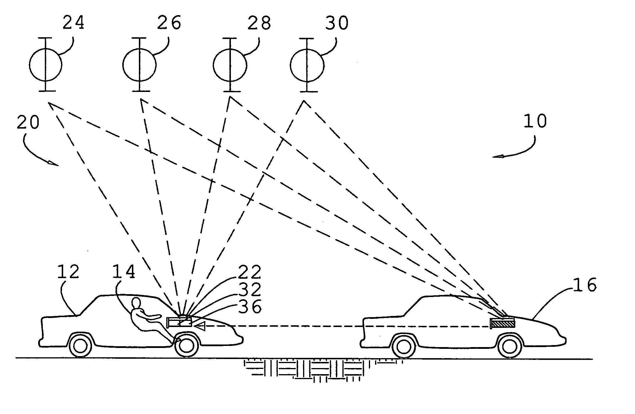
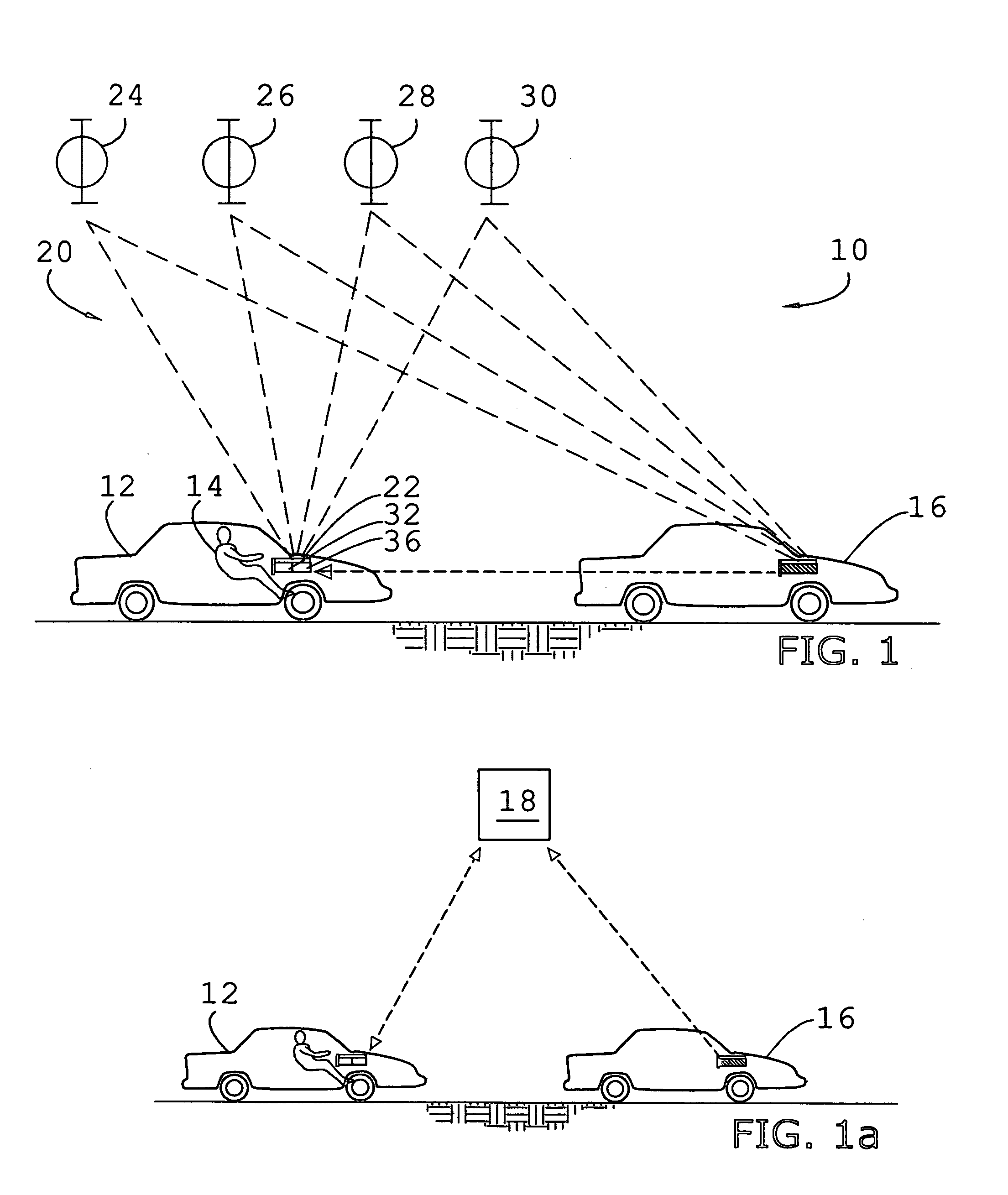
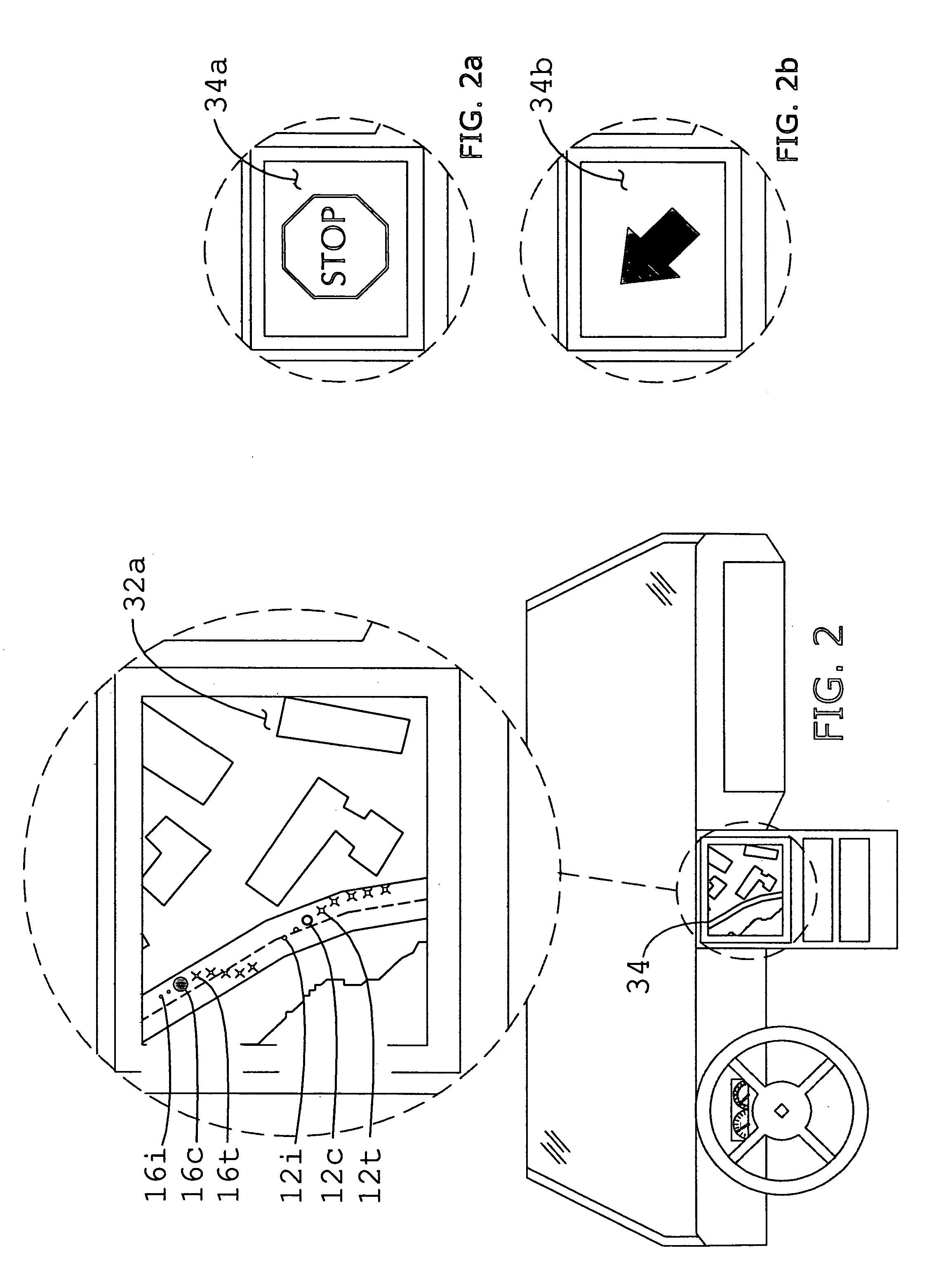
[0026] As shown in FIG. 1, the present invention concerns an improved collision control and path prediction system 10 adapted for use with a host vehicle 12 and by an operator 14. The system 10 is illustrated and described herein with respect to vehicles, such as cars, SUV's, trucks, etc. However, it may also be utilized with aircrafts, watercrafts, human motility, or other modes of transportation where projected path prediction or collision avoidance is desired. The system 10 is configured to determine a plurality of trail coordinates 12t, a current position coordinate 12c, and a plurality of immediate dynamic path (“IDP”) coordinates 12i, for the host vehicle 12, and a similar set of coordinates 16t,16c,16i for at least one remote vehicle 16 (see, FIG. 2). Except where a plurality is necessary for discussion, the present invention shall hereinafter be described with respect to a remote vehicle 16, with the understanding that the inventive aspects of the invention may be concurrent...


PUM


Abstract

A collision detection and path prediction system (10) adapted for use with a traveling host vehicle (12) having an operator, includes a locator device (20) configured to determine the current position coordinates, and pluralities of trail and immediate dynamic path coordinates of the vehicle (12) and a communicatively coupled traveling remote vehicle (16). The system further includes a preferred controller (36) configured to predict a collision between the two vehicles (12,16) from the coordinates, and determine a plurality of projected path coordinates for the host vehicle (12) relative to the remote vehicle (16) trail coordinates.

Description

BACKGROUND OF THE INVENTION [0001] 1. Technical Field [0002] The present invention relates to collision avoidance systems adapted for use with a vehicle, and more particularly to an improved system configured to predict a projected path of a host vehicle, and detect a collision between the host vehicle and at least one other object. [0003] 2. Background Art [0004] Collision control systems have been developed to reduce the likelihood of collisions between transportation machines, such as boats, aircrafts, and automotive vehicles. With respect to vehicles, these conventional safety applications rely upon the ability to determine the accurate relative positioning and predictable driving trajectories of the host and the surrounding vehicles to provide forward collision warning and effect automated braking in certain instances. In general, to identify the target vehicles that pose collision threats, current state of the art approaches use inputs from a variety of external vehicle sensor...

Claims


Application Information

Patent Timeline
Patent Type & Authority Applications(United States)
IPC IPC(8): B60T8/32G01C21/00
CPCB60T7/22G01C21/00G08G1/163
Inventor MUDALIGE, UPALI PRIYANTHAKELLUM, CARROLL C.
Owner GM GLOBAL TECH OPERATIONS LLC
Why Eureka
Try Eureka