Gas Fireplace

a gas fireplace and gas technology, applied in the field of gas fireplaces, can solve the problems of unsatisfactory heat gradient generation, uneven heating of the room, and considerable increase in noise pollution, and achieve the effects of reducing or at least substantially reducing the above mentioned drawbacks, optimum efficiency, and high yield and autonomy

Inactive Publication Date: 2007-03-01
GRUPPO PIAZZETTA
View PDF7 Cites 14 Cited by
  • Summary
  • Abstract
  • Description
  • Claims
  • Application Information

AI Technical Summary

Benefits of technology

[0010] The main object of the present invention is to provide a gas fireplace which makes it possible to eliminate or at least substantially reduce the above mentioned drawbacks. Another obj

Problems solved by technology

In any case, such a fireplace system is unsuitable for quickly heating room air below the warm air delivery level, where instead a quick warming is desirable as warm air flow obviously tends to flow upwards towards the room ceiling, thus resulting in an undesired heat gradient being generated, at least at the initial stage of heating a room, between the air close to the ceili

Method used


Image

  • Gas Fireplace
  • Gas Fireplace
  • Gas Fireplace

Examples


Embodiment Construction

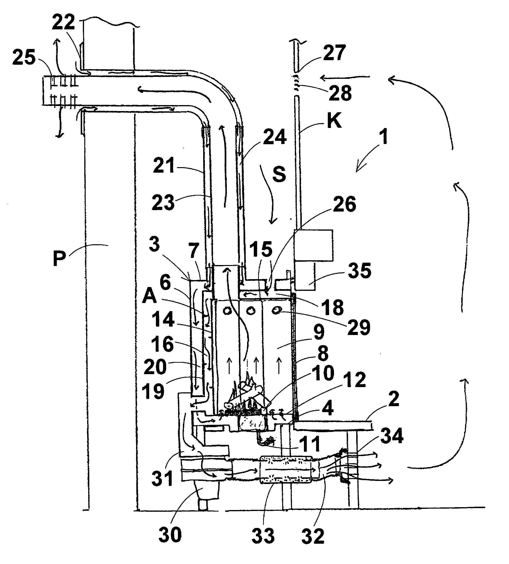
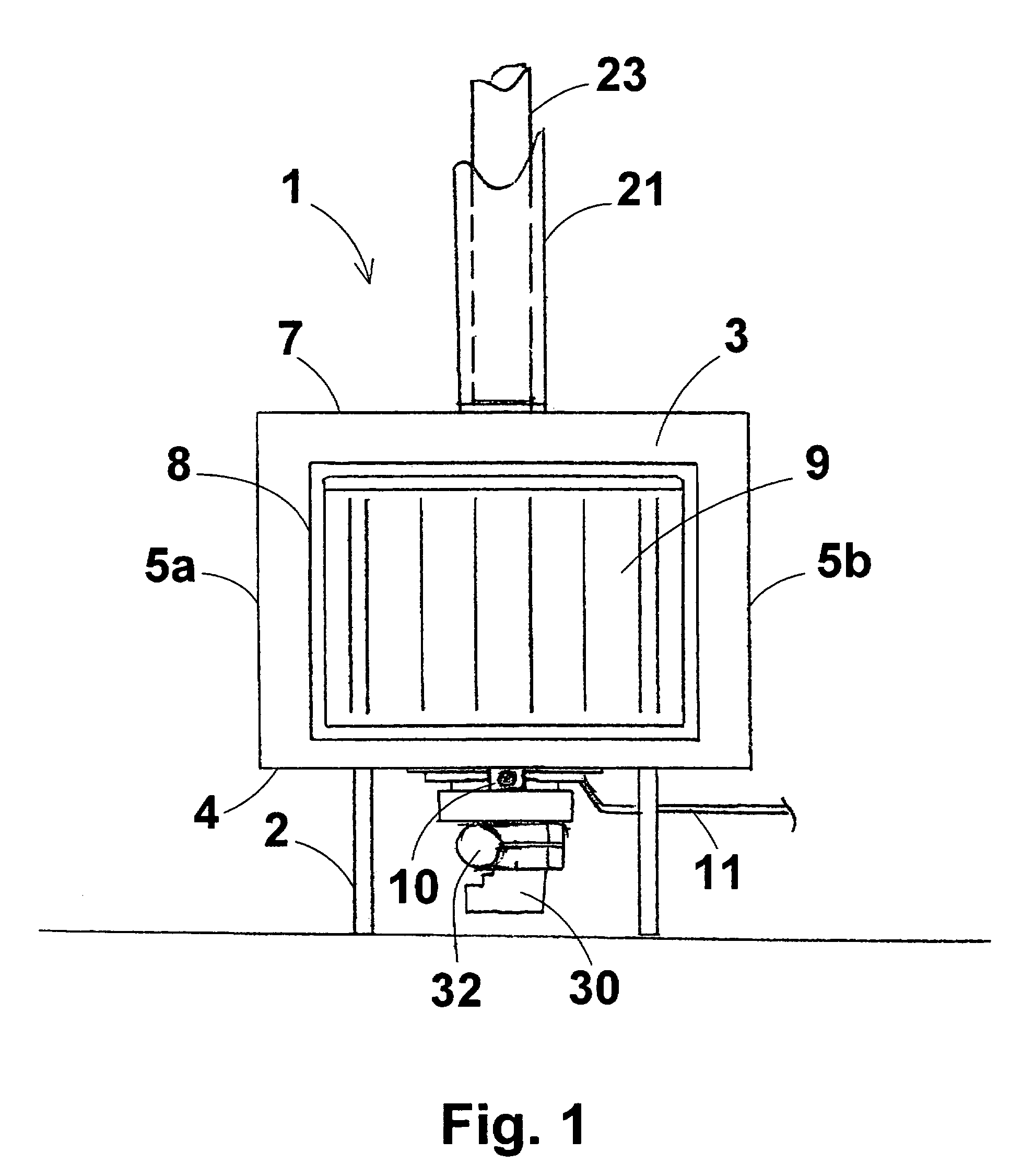
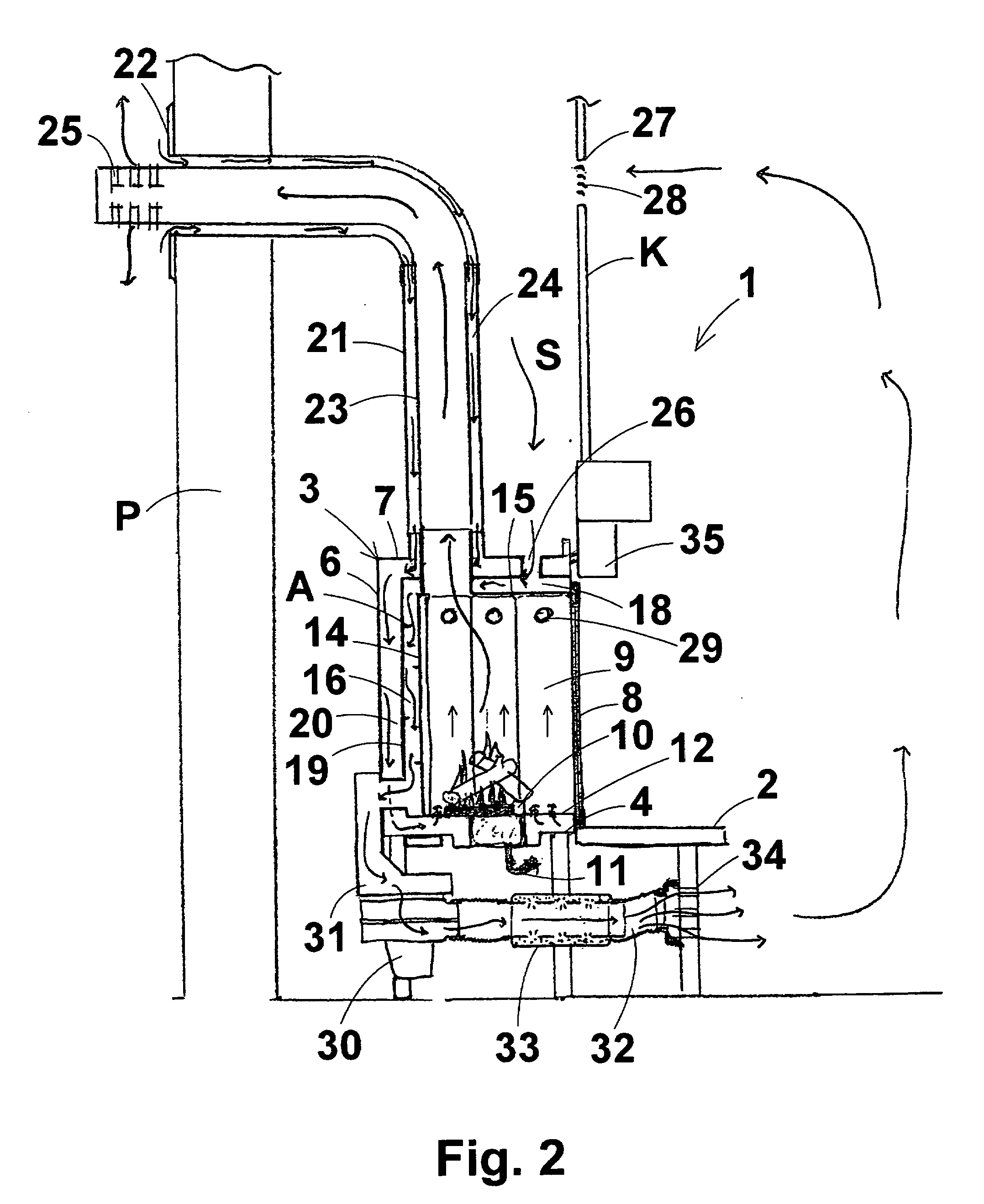
[0023] With reference to the above listed Figures, a gas fireplace according to the present invention, generally designed with reference numeral 1, comprises a support and housing frame including a base 2, preferably covered with lining members, e.g. made of marble or ceramic material, from which a substantially parallelepiped housing 3 rectangular in top view rises. The housing 3 delimits a closed inner space and comprises a lower or bottom wall 4, two side walls 5a, 5b, a rear wall 6, an upper or ceiling wall 7, as well as a front door 8, preferably made of glass or, more preferably, ceramic glass, in order to ensure a good heat-tight arrangement.

[0024] The inner space of the housing 3 is subdivided into a number of adjacent chambers, as described below.

[0025] In the innest portion there is provided a combustion chamber 9, where a gas burner 10 is located, to which fuel gas can be fed through a feeding duct 11 in fluid communication with a suitable fuel gas source (not shown in ...


PUM


Abstract

A gas fireplace comprises a support and housing frame, a gas combustion chamber, at least one chimney duct for releasing flue gases, coming from said combustion chamber, at least one inlet duct for external comburent air leading to said combustion chamber, a ventilation and heating circuit designed to suck environment air, and heat and fed it at least partly into the space where the fireplace is located, and at least one motor-driven fan designed to operate in said ventilation and heating circuit. The gas fireplace further comprises at least one silencer device provided along said ventilation and heating circuit.

Description

FIELD OF INVENTION [0001] The present invention relates to an improved gas fireplace, particularly suitable for heating house spaces. BACKGROUND OF INVENTION [0002] Numerous fireplaces have been proposed in the art that are fed with gas, generally methane gas or, more recently, gpl (liquefied petroleum gas). [0003] Conventional gas fireplaces generally comprise either a frontally closed combustion chamber or a frontally open fireside, a comburent air intake, an exhaust duct for flue gases, and an air circuit designed to suck room air to be heated, to heat the sucked air, and to discharge the heated air into the room where the gas fireplace is located. [0004] Such fireplaces have a number of serious drawbacks. As a matter of fact, room air is sucked from the room where the fireplace is located, typically through openings or mouths formed in the lower portion of the fireplace, is heated mainly owing to convective heat exchange through metal walls of the combustion chamber or fireside,...

Claims


Application Information

Patent Timeline
IPC IPC(8): F24C1/14F24C15/00F24B1/18F24B1/188F24C3/00
CPCF24B1/1808F24C3/002F24C15/003F24C3/004
Inventor CARLO, PIAZZETTA
Owner GRUPPO PIAZZETTA
Why Eureka
Try Eureka