Radiation detector

a detector and radiation technology, applied in the field of radiation detectors, can solve the problems of large moisture permeability, deterioration of sensitivity characteristics or resolution characteristics, and large moisture permeability, and achieve the effect of long-term stability and high sensitivity characteristics

Inactive Publication Date: 2007-03-01
KK TOSHIBA +1
View PDF3 Cites 38 Cited by
  • Summary
  • Abstract
  • Description
  • Claims
  • Application Information

AI Technical Summary

Benefits of technology

[0013] The present invention has been achieved in consideration of the above circumstances, and it is an object of the present invention to provide a radiation detector having high sensitivity characteristics and resolution characteristics with long term stability.

Problems solved by technology

However, since the X-ray conversion film causes material deterioration when allowing it to stand in an air atmosphere, sensitivity characteristics or resolution characteristics deteriorate.
On the contrary, many of the materials used for the scintillator layer have high hygroscopicity, and therefore, when allowing it to stand in an air atmosphere, the sensitivity characteristics or the resolution characteristics deteriorate.
However, the protective film obtained by the evaporation deposition method described above has a small film thickness, and has defects such as pinhole, so that moisture permeability is large.
Further, coating along the substrate end side of the protective layer is insufficient for long time suppression of deterioration of the sensitivity characteristics or the resolution characteristics because the moisture permeability of interface between the substrate and the resin becomes large.
Furthermore, the defect such as the pinhole causes micro discharge in the direct method, which leads to deterioration of the protective film itself.
The protective layer composed of the organic film described above has little defects such as the pinhole immediately after formation, and is hard to generate cracks even with a thin film.
However in a heating process at assembly of the X-ray detector, its temperature exceeds a glass transition temperature (Tg), and thus, there is a fear that defects such as the pinhole occur due to softening and modification.
However, since mechanical strength at a thin film is small, cracks are easy to be generated, and realization of a thick film is not easy.
Then, the formation by means of the evaporation deposition method has problems that it is not easy to obtain the high sensitivity characteristics and the high resolution characteristics with long time stability.
This is because the protective film is deposited in a gap of columnar crystal in the indirect method, and reflection efficiency within the columnar crystal becomes small since a refractive index ratio between the columnar crystal and the gap becomes approximately 1, so that the resolution and luminous efficiency deteriorate.

Method used


Image

  • Radiation detector
  • Radiation detector
  • Radiation detector

Examples


examples

[0102] First, there will be described Example 1 of the epoxy resin to be used for the protective film of the X-ray detector of the present invention.

[0103] 51.7 wt. % of EXA-1000 (epoxy equivalent 343) (trade name: manufactured by Dainippon Ink and Chemicals, Incorporated), 17.5 wt. % of D-400 (an active hydrogen equivalent 116) (trade name: manufactured by Sun Techno Chemicals, Co., Ltd.), 0.15 wt. % of a surfactant, 30.12 wt. % of spherical silica, and 0.53 wt. % of a carbon based colorant were compounded and then mixed by a rotation and revolution type mixing apparatus to prepare a first epoxy resin.

[0104] Next, there will be described Example 2 of the epoxy resin to be used for the protective film of the X-ray detector of the present invention.

[0105] 47.85 wt. % of EP-4000S (epoxy equivalent 260) (trade name: manufactured by Asahi Denka Kogyo K.K.), 21.35 wt. % of D-400 (an active hydrogen equivalent 116) (trade name: manufactured by Sun Techno Chemicals, Co., Ltd.), 0.15 wt....


PUM


Abstract

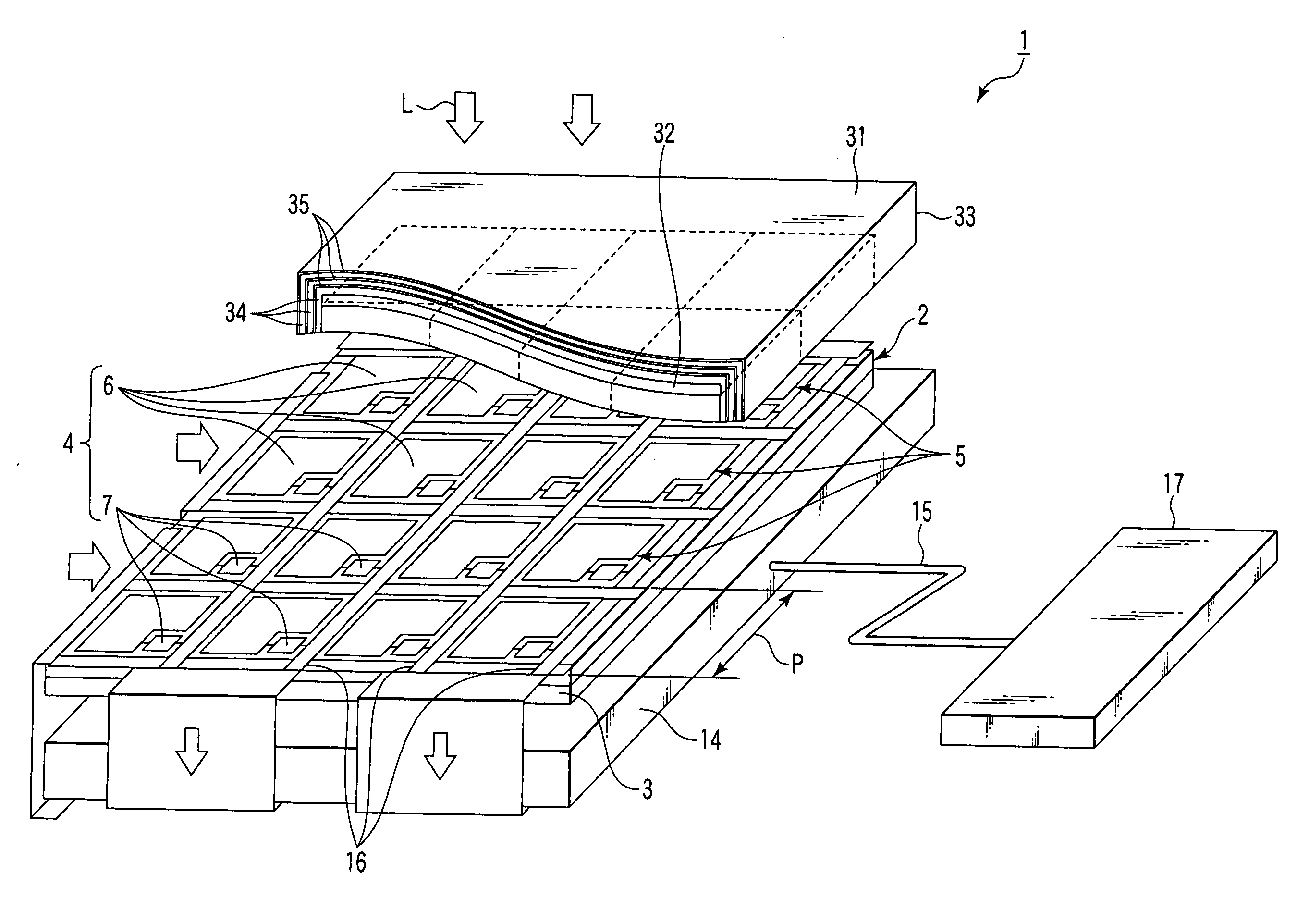
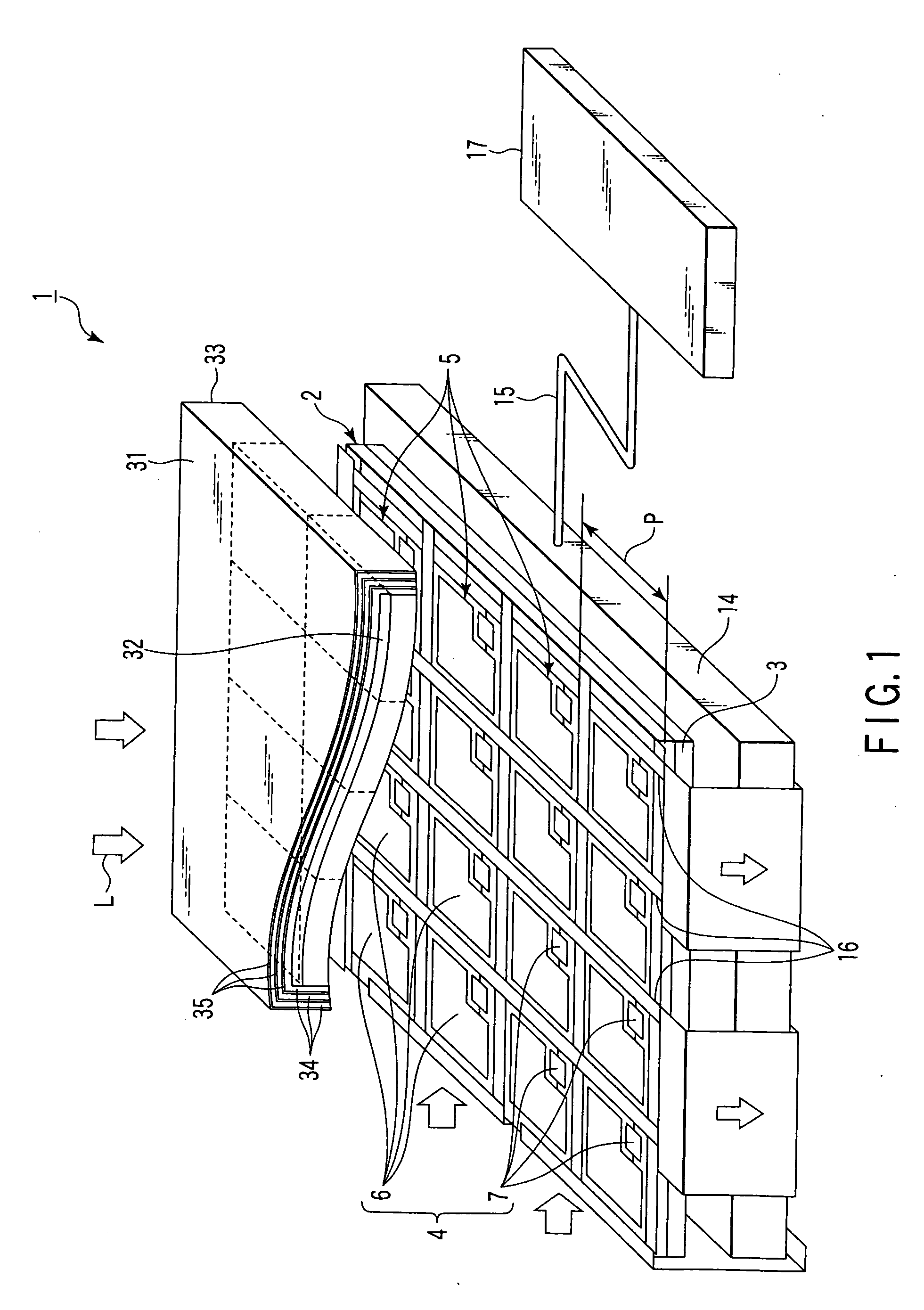
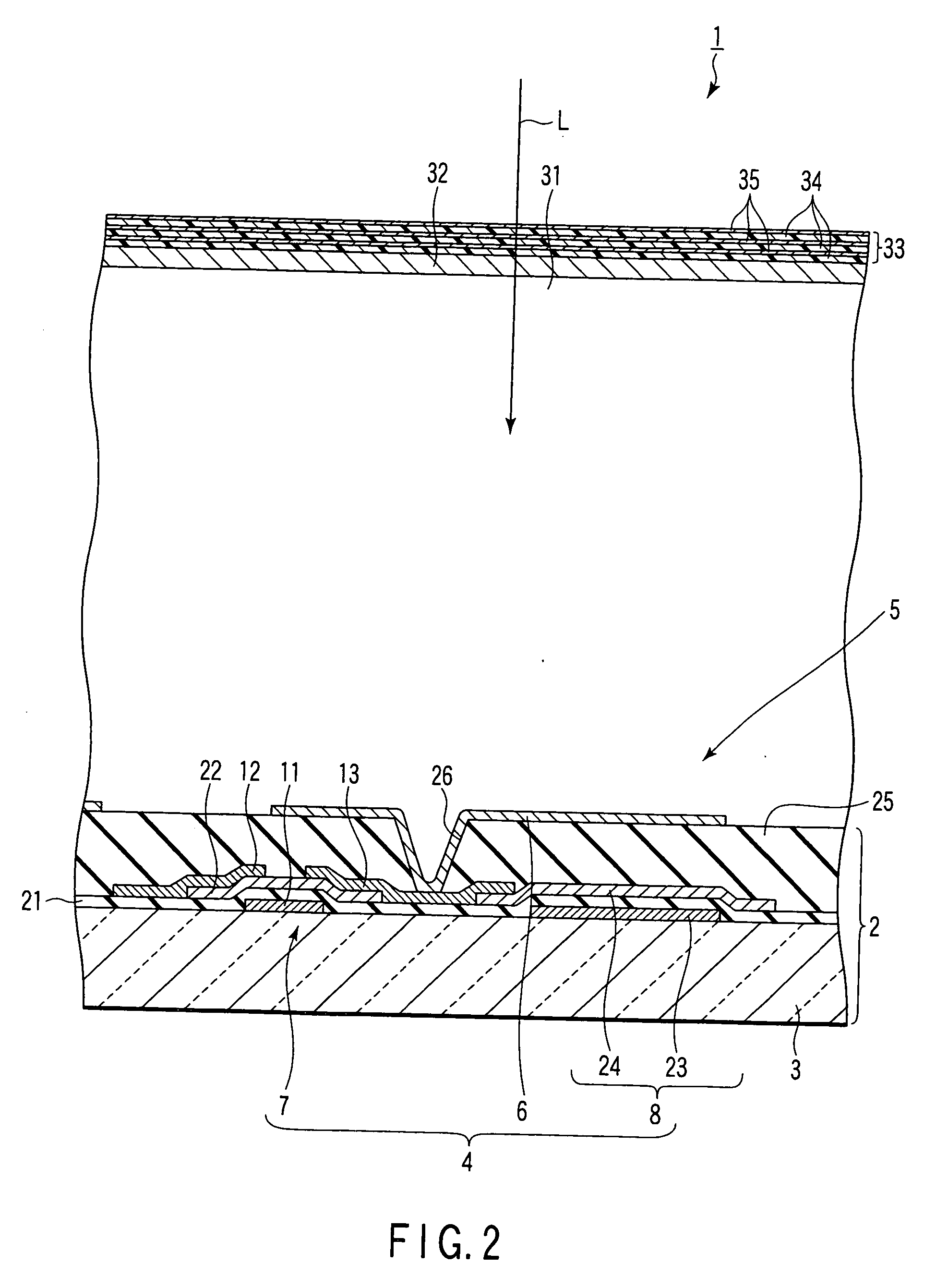
A radiation detector comprises an electrode substrate, pixel electrodes provided on the electrode substrate, and detecting electric signals, a radiation conversion layer provided on the pixel electrodes, and converting incident radiations into electric signals, upper electrodes provided at a position on the radiation conversion layer opposite to the pixel electrodes, and a protective layer provided on the upper electrode, the protective layer having a flexural modulus not more than a flexural modulus of the electrode substrate.

Description

CROSS-REFERENCE TO RELATED APPLICATIONS [0001] This application is based upon and claims the benefit of priority from prior Japanese Patent Application No. 2005-246007, filed Aug. 26, 2005, the entire contents of which are incorporated herein by reference. BACKGROUND OF THE INVENTION [0002] 1. Field of the Invention [0003] The present invention relates to a radiation detector for converting incident radiations into electric signals. [0004] 2. Description of the Related Art [0005] An active matrix type planar detector has been developed as an X-ray diagnostic image detector of new-generation. The planar detector detects irradiated X-rays, whereby an X-ray photographed image or an X-ray image in real time is output as a digital signal. [0006] Then, there are two methods of a direct method and an indirect method as being classified largely in this kind of the planar detector. The direct method is a method for acquiring an image in such a manner as to convert the X-ray into a charge sig...

Claims


Application Information

Patent Timeline
Patent Type & Authority Applications(United States)
IPC IPC(8): G01T1/20G01T1/24
CPCG01T1/2928G01T1/2018G01T1/20189
Inventor WAKAMATSU, SHUNSUKEFUJIEDA, SHINETSU
Owner KK TOSHIBA
Why Eureka
Try Eureka