Sensor

a technology of sensors and electrodes, applied in the field of sensors, can solve the problems of easy vibration of the electrode plate, and achieve the effects of reducing noise added to the pressure signal, facilitating electrical isolation, and reducing stress

Inactive Publication Date: 2007-03-01
SANYO ELECTRIC CO LTD
View PDF0 Cites 28 Cited by
  • Summary
  • Abstract
  • Description
  • Claims
  • Application Information

AI Technical Summary

Benefits of technology

[0009] In the sensor according to the first aspect of the present invention, the support having the higher elastic modulus is so formed as to cover at least two of the upper surface and the lower surface of the electrode plate and the side surface of the hole so that bearing strength of the support for the electrode plate can be further improved as compared with a case of forming the support to cover only the upper or lower surface of the electrode plate, thereby inhibiting the electrode plate from vibration. Thus, only the diaphragm can remarkably vibrate when the sensor receives a sound or the like, so that change in the electrostatic capacitance between the diaphragm and the electrode plate can be increased. Consequently, the change in the electrostatic capacitance between the diaphragm and the electrode plate can be so increased as to increase an electric signal output from the sensor. When the support having the higher elastic modulus supports both of the upper and lower surfaces of the electrode plate maximumly expanded or contracted to receive maximum tensile stress and maximum compressive stress upon vibration of the electrode plate and the support, bearing strength of the support for the electrode plate can be improved also when the total thickness of parts of the support formed on the upper and lower surfaces of the electrode plate respectively is identical to the thickness of a support formed only on the upper or lower surface of the electrode plate. Thus, the bearing strength for the electrode plate can be improved without increasing the thickness of the support dissimilarly to a case of supporting only the upper or lower surface of the electrode plate with the support, thereby preventing the support from cracking resulting from an increased thickness thereof.
[0028] A sensor according to a second aspect of the present invention comprises a first electrode provided on a semiconductor substrate, a second electrode opposed to the first electrode at a prescribed interval for constituting a capacitor with the first electrode and an insulating film provided on at least the upper surface of the second electrode for fixing the second electrode to the semiconductor substrate. An impurity is introduced into the insulating film by ion implantation. According to modification employing ion implantation, the temperature of the insulating film is substantially increased to about 800° C. during implantation of the impurity, so that the insulating film is densified. At this time, the insulating film is densified while bonds therein are cut due to the implanted impurity, so that the insulating film is relieved from stress. After implantation of the impurity, the insulating film develops expansive force when returning from the temperature of about 800° C. to an equilibrium state of the room temperature, to result in compressive stress (stress acting in an expansive direction with respect to an underlayer) applied to the insulating film. Thus, compressive stress (stress acting in the expansive direction with respect to the underlayer) is applied to the insulating film due to ion implantation, to fix the electrode plate in an outwardly pulled state (in the expansive direction with respect to the underlayer). When a pressure is applied to the second electrode, therefore, the second electrode is inhibited from vibration (displacement). Consequently, noise added to a pressure signal is reduced as compared with a case of employing an insulating film subjected to no ion implantation, whereby the sensor has low noise to be capable of correctly measuring capacitance change.

Problems solved by technology

In the sonic sensor according to the aforementioned National Patent Publication Gazette No. 2004-506394, however, the support supports only the upper surface of the electrode plate, leading to such a disadvantage that the electrode plate easily vibrates.

Method used


Image

  • Sensor
  • Sensor
  • Sensor

Examples


first embodiment

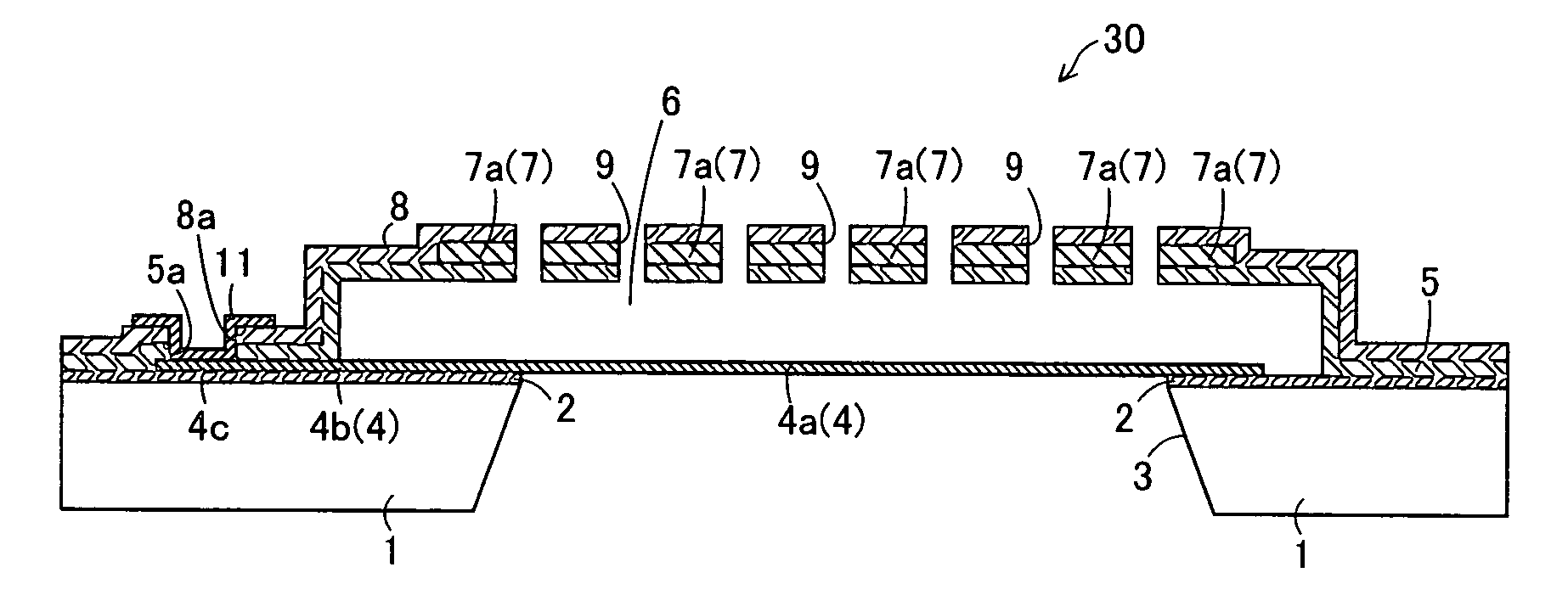
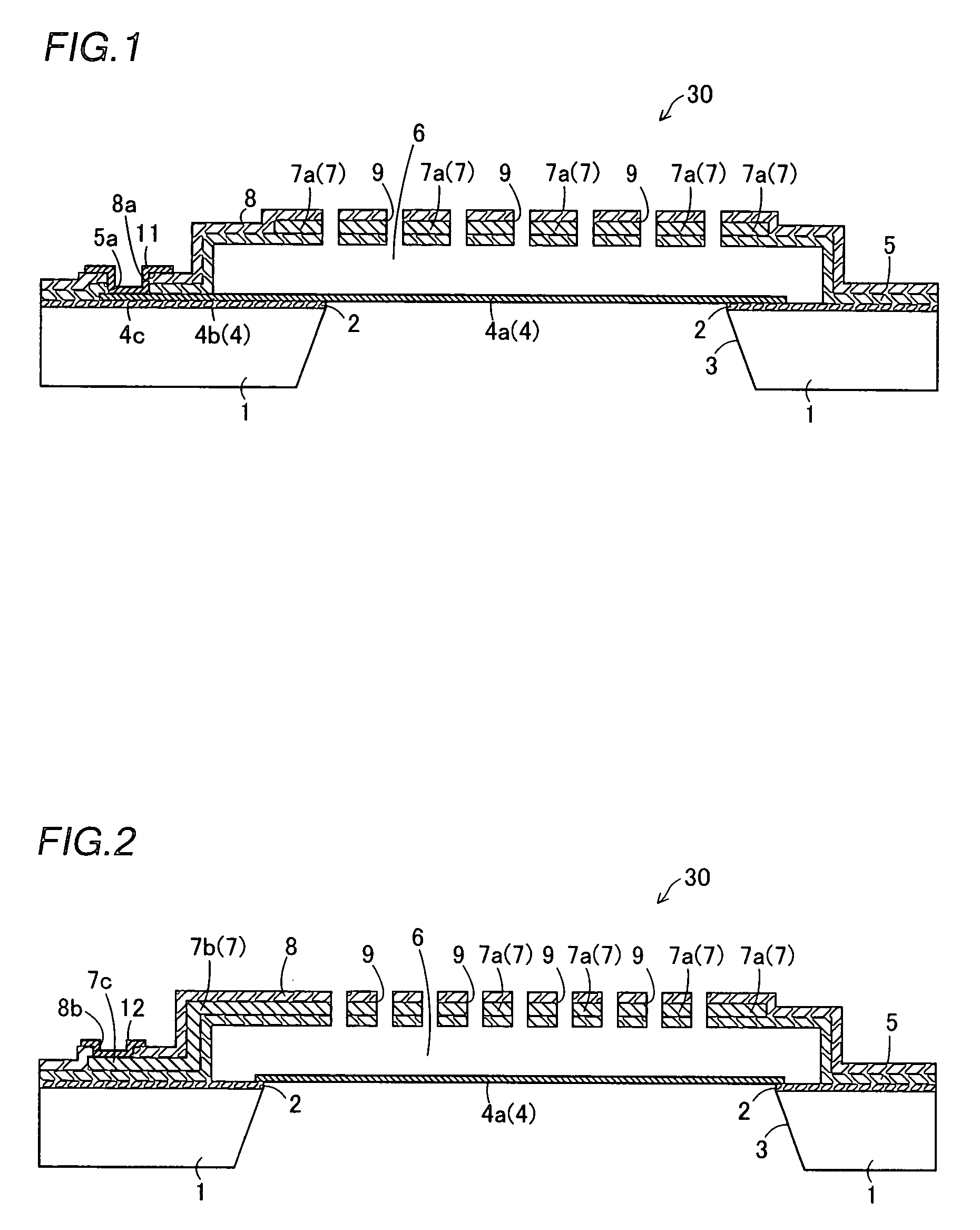
[0049] The structure of a microphone 30 according to a first embodiment of the present invention is described with reference to FIGS. 1 to 4.

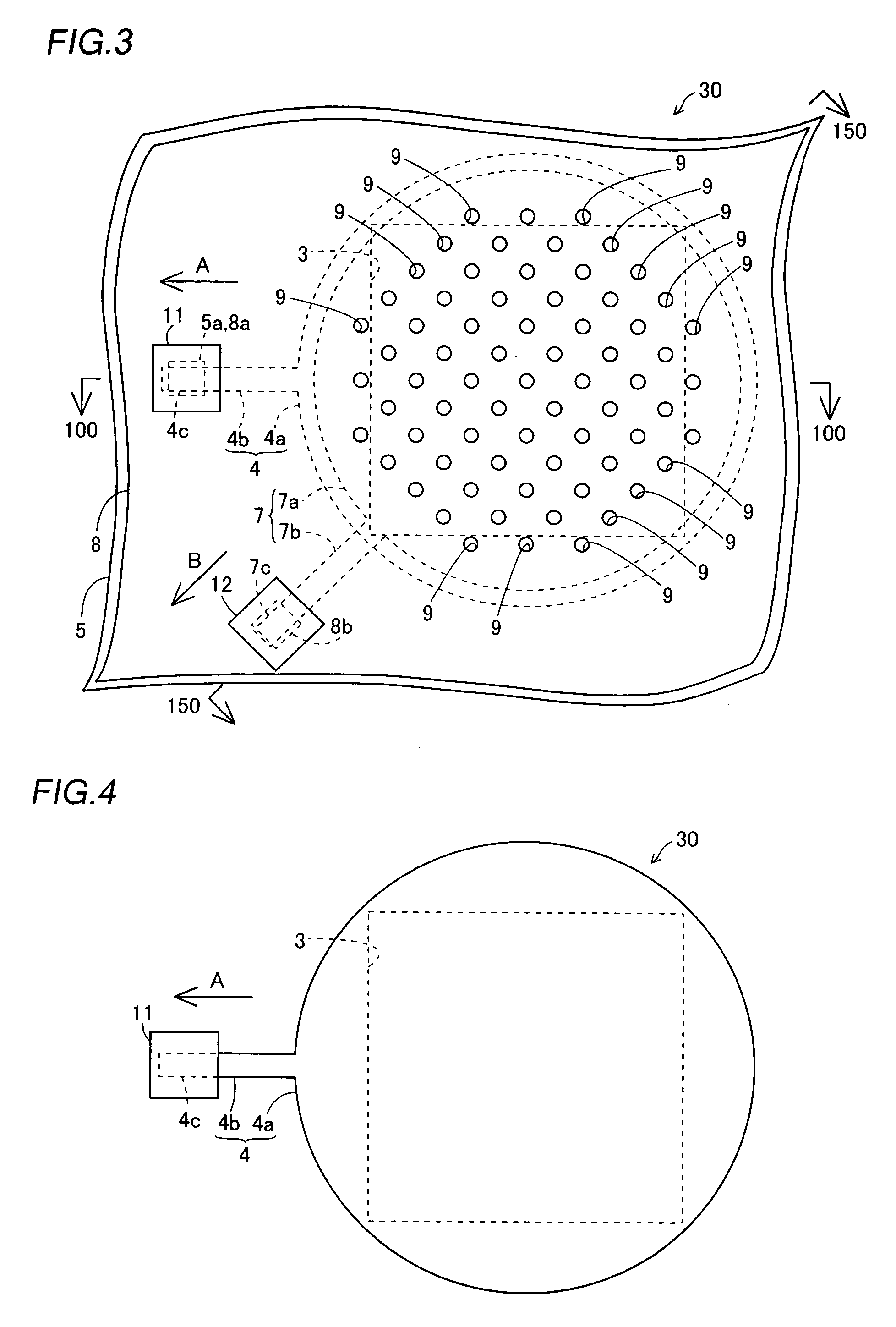
[0050] In the microphone 30 according to the first embodiment, an etching stopper layer 2 of SiN is formed on the surface of a silicon substrate 1, as shown in FIGS. 1 and 2. This etching stopper layer 2 has a thickness of about 0.05 μm to about 0.2 μm. A partially square-pyramidal (truncated square-pyramidal) opening 3 (see FIGS. 1 and 3) is formed in a region formed with a diaphragm 4a described later, to pass through the silicon substrate 1 and the etching stopper layer 2. This opening 3 functions as an air passage when the microphone 30 receives a sound.

[0051] A polysilicon layer 4 having a thickness of about 0.1 μm to about 2.0 μm is formed on the upper surfaces of the etching stopper layer 2 and the opening 3. This polysilicon layer 4 is doped with an n-type impurity (phosphorus (P)), to be conductive. As shown in FIGS. 3 and 4, the pol...

second embodiment

[0089] Referring to FIG. 31, supports are formed not only on the upper and lower surfaces of an electrode plate portion 47a but also on the inner side surfaces of holes 47b of the electrode plate portion 47a corresponding to sonic holes 49 in a microphone 30a according to a second embodiment of the present invention, dissimilarly to the aforementioned first embodiment.

[0090] In the microphone 30a according to the second embodiment, the holes 47b larger than the sonic holes 49 are formed in the electrode plate portion 47a of a polysilicon layer 47 on positions corresponding to the sonic holes 49, as shown in FIG. 31. An upper support layer 48 is so formed as to cover not only the upper surface of the electrode plate portion 47a of the polysilicon layer 47 but also the side surfaces of the holes 47b of the electrode plate portion 47a. A lower support layer 45 is so formed as to cover portions of the polysilicon layer 47 located on the lower ends of the inner side surfaces of the hole...

third embodiment

[0100] A sonic sensor 300 according to a third embodiment of the present invention is described with reference to FIGS. 37 to 39. According to the third embodiment, modified SiOC layers 308a formed by ion implantation are employed as supports supporting electrode plates (fixed electrodes), dissimilarly to the aforementioned first and second embodiments.

[0101] As shown in FIGS. 37 to 39, the sonic sensor 300 according to the third embodiment comprises a vibrating electrode 304 constituting a diaphragm formed on a silicon substrate 301 and fixed electrodes 306 opposed to the vibrating electrode 304 and arranged at prescribed intervals. The vibrating electrode 304 and the fixed electrodes 306 constitute capacitors.

[0102] The sonic sensor 300 includes the silicon substrate 301, an etching stopper layer 302a, the vibrating electrode 304, a sacrifice layer 305, the fixed electrodes 306, sonic holes 307a, the modified SiOC layers 308a, a pad electrode 309a for the vibrating electrode 304...


PUM


Abstract

A sensor capable of increasing an electric signal output therefrom by inhibiting an electrode plate from vibration is obtained. This sensor comprises a diaphragm provided in a vibrative manner, an electrode plate, opposed to the diaphragm at a prescribed distance, having a hole and a support made of a material having an elastic modulus higher than the elastic modulus of a material constituting the electrode plate for supporting the electrode plate. The support is so formed as to cover at least two of the upper surface and the lower surface of the electrode plate and the side surface of the hole.

Description

BACKGROUND OF THE INVENTION [0001] 1. Field of the Invention [0002] The present invention relates to a sensor, and more particularly, it relates to a sensor having a support supporting an electrode plate. [0003] 2. Description of the Background Art [0004] A sensor such as a sonic sensor converting a sound to an electric signal by change in the electrostatic capacitance between a sonically vibrating diaphragm and an electrode plate is known in general, as disclosed in National Patent Publication Gazette No. 2004-506394, for example. [0005] The aforementioned National Patent Publication Gazette No. 2004-506394 discloses a sonic sensor comprising a vibrative diaphragm, an electrode plate and a support supporting the electrode plate. When this sonic sensor receives a sound, the diaphragm so vibrates as to change the electrostatic capacitance between the diaphragm and the electrode plate, subjected to application of a constant voltage. Charges move from the diaphragm and the electrode pl...

Claims


Application Information

Patent Timeline
Patent Type & Authority Applications(United States)
IPC IPC(8): H01L29/84G01R27/26
CPCH04R19/005
Inventor MATSUBARA, NAOTERUNARUSE, YOHKO
Owner SANYO ELECTRIC CO LTD
Why Eureka
Try Eureka