Aircraft flat panel display system with graphical image integrity

Active Publication Date: 2007-03-01
INNOVATIVE SOLUTIONS & SUPPORT
View PDF12 Cites 29 Cited by
  • Summary
  • Abstract
  • Description
  • Claims
  • Application Information

AI Technical Summary

Benefits of technology

[0015] If desired, a hardware comparator can also be utilized with the present invention to compare a subset of image pixels articulated by the integrity checking function against the video image for reporting any mismatches to the integrity checking function, as opposed to the software comparato

Problems solved by technology

Anti-aliasing of display data, however, is extremely computationally intensive—typically 800 billion instructions/second—since it is necessary to compute the locus of points along each line, arc, etc. and the intensity levels of the adjacent pixels (i.e. those pixels adjacent to the computed data points) for smoothing of the graphical lines and images to be displayed.
To avoid this high computational overhead many such displays use principally-vertical scales which do not require anti-aliasing of the image lines but which limit the ability of graphically-generated flight instruments to either graphically-depict (i.e. mimic) the conventional mechanical instruments with which the flight crew is familiar or present the flight instrument data in other convenient, legible, easily-utilized and readily understandable formats.
However, the size of this code and the complexity of the displays, especially in these new large formats, raises in the avionics industry the problem of having to test all code intended for use on an aircraft to the exacting standards required by the FAA(Federal Aviation

Method used


Image

  • Aircraft flat panel display system with graphical image integrity
  • Aircraft flat panel display system with graphical image integrity
  • Aircraft flat panel display system with graphical image integrity

Examples


Embodiment Construction

)

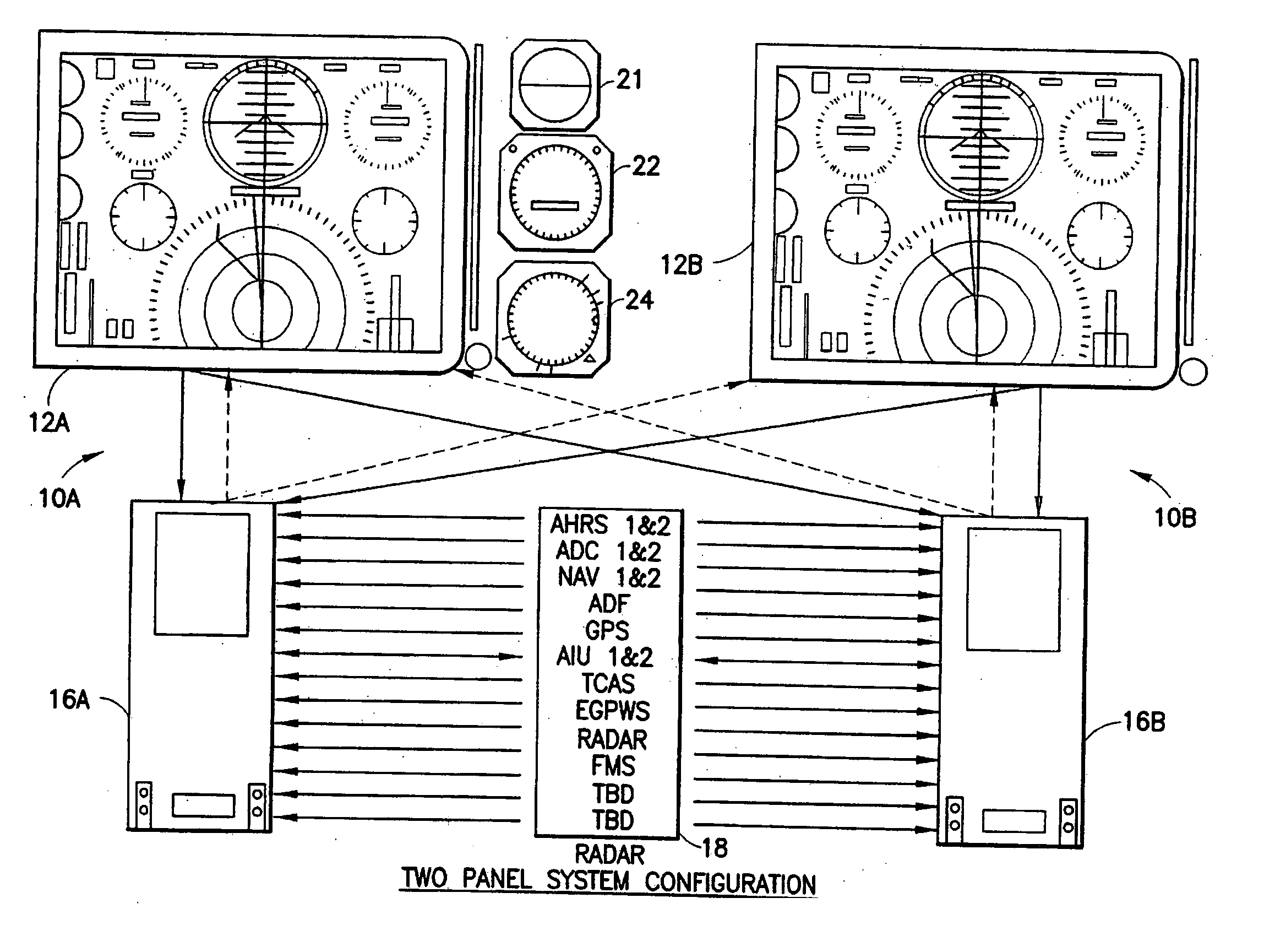
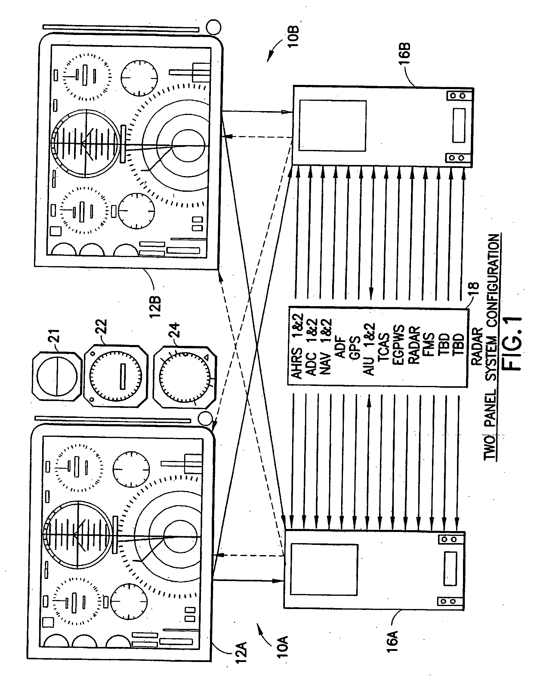
[0028]FIG. 1 depicts an implementation of an aircraft flight panel dual display system constructed in accordance with the system of U.S. Pat. No. 6,693,558 (“the '558 patent”) of the present invention is an improvement thereon as will be described with reference to FIGS. 7-10.

[0029] However, in order to understand the improved system of FIGS. 7-10 better, the '558 system shall be described first with respect to FIGS. 1-6.

[0030] Dual control stations, e.g. a pilot station and a co-pilot station, are generally present in commercial aircraft and, accordingly, a first display system 10A and a second display system 10B are shown. In the disclosed system of the '558 Patent, the display systems 10A and 10B are functionally and structurally alike and equivalent to each other. For convenience and ease of description, a single such system, generically designated by reference number 10, will now be described and discussed. It will in any event be appreciated that the '558 system is equally ...


PUM


Abstract

An improvement over prior art aircraft instrument flight display systems for imaging on a bit-mapped display formed of a multiplicity of individually addressable pixels at locations throughout the display and actuatable to create images on the display, employs a common processor operatively connected between a video graphics processor and the display system input of a common set of aircraft and environmental sensor data—to provide both an integrity checking function and a graphics rendering function in which the integrity checking function can directly check the images generated by the graphics rendering function without the need for comparator hardware. Separate processors may also be employed instead of a common processor. The integrity checking function uses the input information for generating a pixel verification map for checking the display based on pixel color and location. The system can also check for pitch and roll accuracy as well as check the integrity of complex images using statistical detection.

Description

[0001] This application is related to commonly owned U.S. Pat. No. 6,693,558, filed Dec. 14, 2001, issued Feb. 17, 2004, naming Geoffrey S. M. Hedrick as the sole inventor, and is an improvement thereon. The contents of U.S. Pat. No. 6,693,558 are hereby specifically incorporated by reference in their entirety.BACKGROUND OF THE INVENTION [0002] 1. Field of the Invention [0003] The present invention relates to flat panel flight instrument displays for use in aircraft. [0004] 2. Description of the Related Art [0005] It is essential in the creation of graphical flight instruments for an aircraft that are to be used and relied upon by the flight crew that they be of ultra high reliability and integrity. [0006] In prior art systems, the Pilot Flight Display (PFD), Navigation Display (ND) and Engine / Electrical Display (ICAS) systems of an aircraft receive sensor data / inputs on all relevant parameters—about 100 pieces of data, the majority in the standard ARINC 429 serial format. This data...

Claims


Application Information

Patent Timeline
IPC IPC(8): G06T11/20
CPCG01C23/00G06F3/1415G09G2380/12G09G2360/18G09G2340/10G09G2330/12
Inventor HEDRICK, GEOFFREY S.M.ASKARPOUR, SHAHRAMKNOPF, MARKUSCOLLINS, JEFF
Owner INNOVATIVE SOLUTIONS & SUPPORT
Why Eureka
Try Eureka