

Liquid crystal display
a liquid crystal display and liquid crystal technology, applied in the field of liquid crystal display, can solve the problems of increasing the size of the liquid crystal display, increasing the power consumption, and increasing the heat generation, so as to reduce the light utilization efficiency enhance the brightness in the oblique direction, and minimize the effect of liquid crystal display
- Summary
- Abstract
- Description
- Claims
- Application Information
AI Technical Summary
Benefits of technology
Problems solved by technology
Method used
Image

Examples
example 1
(Synthesis of Polymer X)
[0208] Charged into a glass flask fitted with a stirrer, two dripping funnels, a gas feeding tube, and a thermometer were 40 g of a mixture of Monomers Xa and Xb of the type and ratio described in Table 1, 2 g of mercaptopropionic acid as a chain transfer agent, and 30 g of toluene. The resulting mixture was heated to 90° C. Thereafter, 60 g of the mixture of Monomers Xa and Xb of the type and ratio described in Table 1 was dripped over 3 hours from one dripping funnel, while 0.4 g of azobisisobutyronitrile dissolved in 14 g of toluene was simultaneously dripped from the other dripping funnel over 3 hours. Thereafter, 0.6 g of azobisisobutyronitrile, dissolved in 56 g of toluene, was dripped over 3 hours, followed by reaction for an additional 2 hours, whereby Polymer X was prepared. The weight average molecular weight of Polymer X was determined employing the method described above.
(Synthesis of Polymer Y)
[0209] Block polymerization was carried out base...
example 2
[0224] A hard coat layer was applied onto Cellulose Ester Film 2, described in Table 1, based on the following steps.
Acryl monomer: KAYARAD DPHA220 parts by weight(dipentaerythritolhexaacrylate, produced byNippon Kayaku Co., Ltd.)IRUGACURE 184 (produced by Ciba 20 parts by weightSpecialty Chemicals Co.,Ltd.)Propylene glycol monomethyl110 parts by weightetherEthyl acetate110 parts by weight
[0225] The above hard coat layer liquid composition was filtered via a polypropylene filter of a core diameter of 0.4 μm and subsequently applied onto Cellulose Ester 2 described in Table 1, employing a micro-gravure coater. After drying the coating at 90° C., the resulting coating was cured under conditions in which by employing a UV lamp, illuminance in the exposed area was set at 100 mW / cm2 and the exposure amount was set at 0.1 J / cm2, and a hard coat layer at a dried layer thickness of 5 μm was formed, whereby Hard Coat Film 1 was prepared.
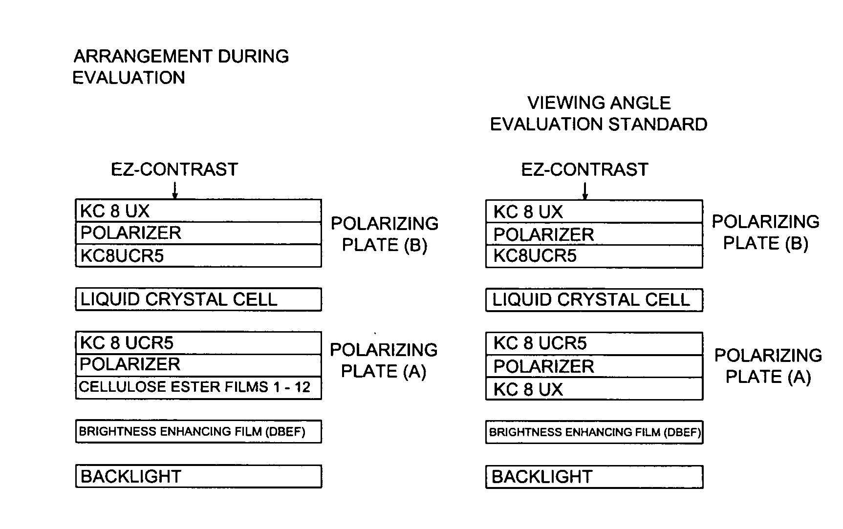
[0226] A liquid crystal display was prepared in the ...
example 3
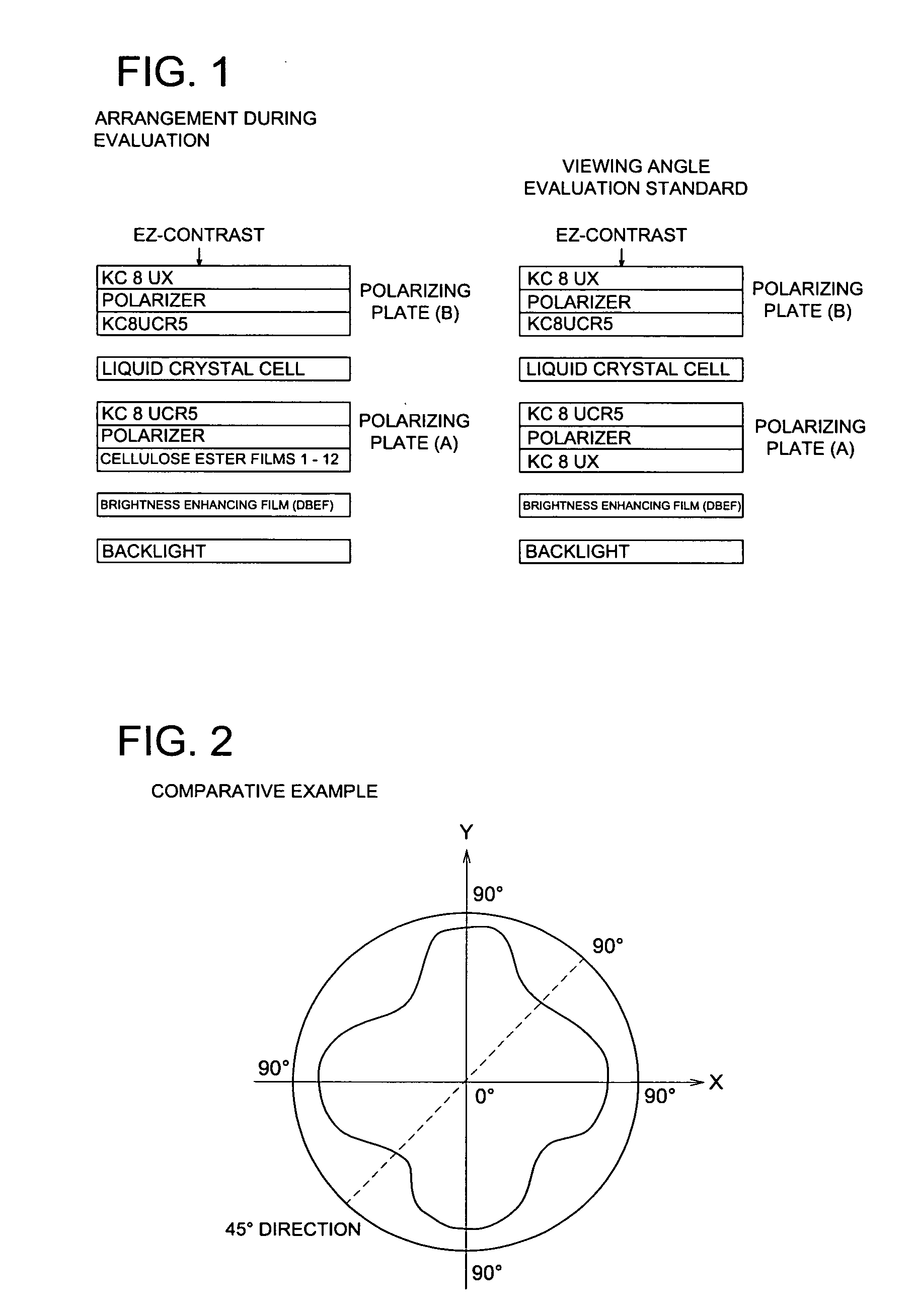
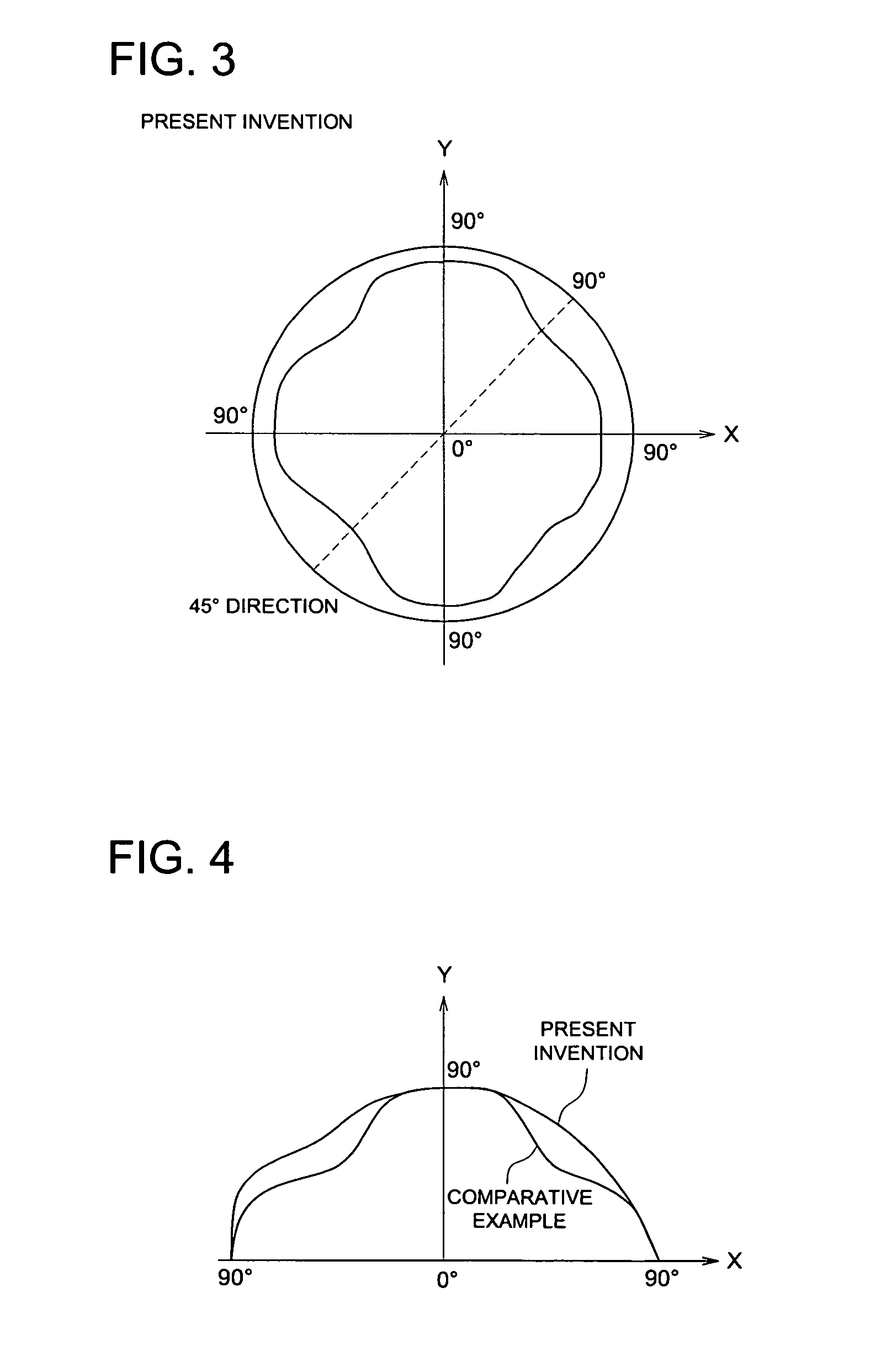
Using liquid crystal displays employing polarizing plates 2 and 8 of Example 1, the brightness of the display in an oblique direction of 45°, while a white image was displayed, was relatively evaluated.
[0228] The orientation property of brightness (luminance) was measured using a spectroradiometer CS-1000A produced by Konica Minolta Sensing, Inc. The sensor of the spectroradiometer CS-1000A was placed on a normal line of a liquid crystal display panel at a certain point which was designated as point A. The sensor was then gradually inclined to 45° direction of the liquid crystal display panel (upward direction of the liquid crystal display panel was designated as 0°), while the sensor was heading to point A and keeping the same distance from point A. The luminance of the liquid crystal display panel was measured at incline angles in the range of 0° to 90°, provided that the incline angle was set to 0° when the sensor was on the normal line of the liquid crystal display panel at po...
PUM
 Abstract
Description
Claims
Application Information