Clock and data recovery circuit having wide phase margin

a clock and data recovery circuit technology, applied in the direction of digital transmission, pulse automatic control, synchronisation signal speed/phase control, etc., can solve the problems of u.s. pat, difficult to adapt to the spread spectrum clocking (ssc), etc., and achieve the effect of wide phase margin and high speed

Inactive Publication Date: 2007-03-01
SAMSUNG ELECTRONICS CO LTD
View PDF6 Cites 51 Cited by
  • Summary
  • Abstract
  • Description
  • Claims
  • Application Information

AI Technical Summary

Benefits of technology

[0026] Therefore, the CDR circuit may recover data and a clock signal

Problems solved by technology

The methods according to U.S. Pat. No. 6,002,279 and U.S. Pat. No. 6,122,336, however, are difficult to adapt to spread spectrum clocking (SSC).
In addition, an error between adjacent circuits may be increased because of electromagnetic interference (EMI).
Therefore, there exist limits as to how much a clock frequency can be increased.
It is difficult, however, to increase the operating speed and the frequency variation to more than 300 MHz and 2,000 ppm, respectively, in the phase detector and loop filter of a generic digital logic circuit.
The

Method used


Image

  • Clock and data recovery circuit having wide phase margin
  • Clock and data recovery circuit having wide phase margin
  • Clock and data recovery circuit having wide phase margin

Examples


Embodiment Construction

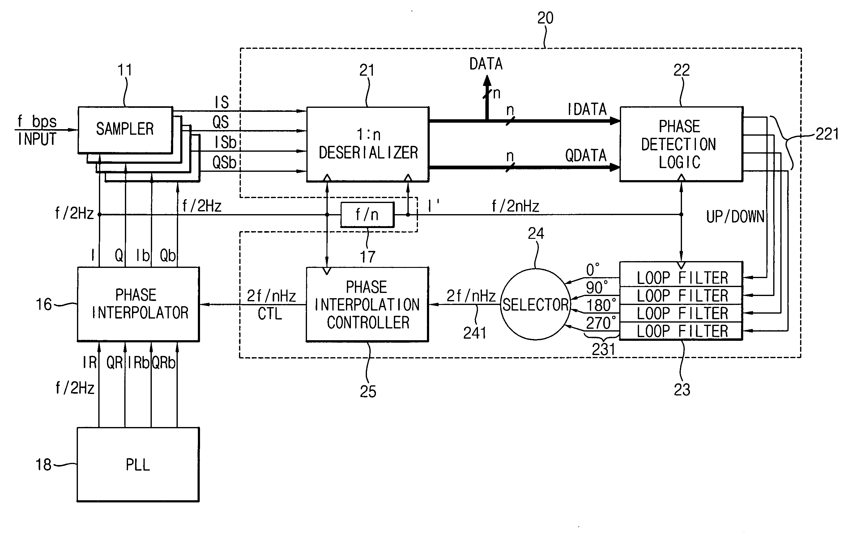
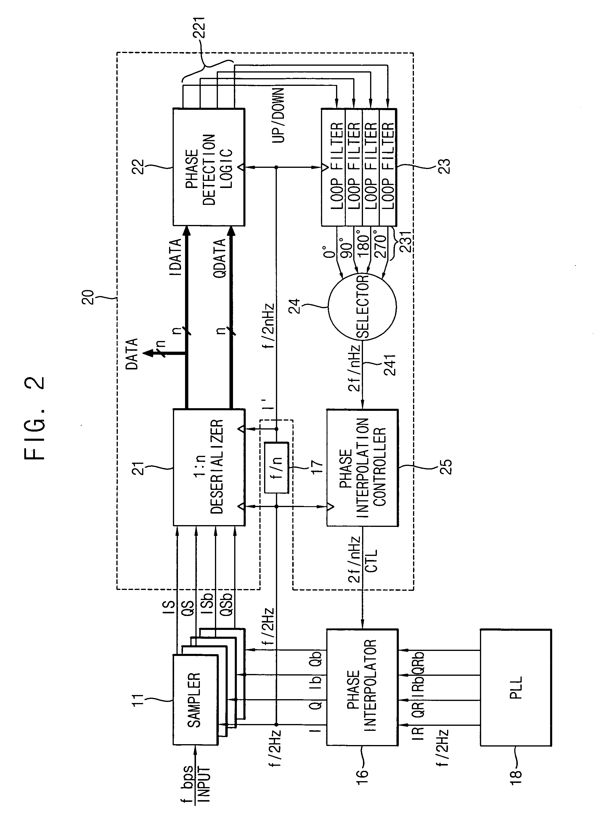
[0036]FIG. 2 is a block diagram illustrating a clock and data recovery (CDR) circuit according to an exemplary embodiment of the present invention.

[0037] Referring to FIG. 2, the CDR circuit includes a sampler 11, a phase interpolator 16, a frequency divider 17, a phase-locked loop 18 and a clock and data recovery loop 20. The clock and data recovery loop 20 includes a deserializer (serial-parallel converter) 21, a phase detection logic 22, a loop filter 23, a selector 24, and a phase interpolation controller 25.

[0038] The phase-locked loop 18 generates four reference clock signals IR, QR, IRb and QRb that respectively have a frequency of f / 2 Hz and a phase difference of about 90° between each other. The four reference clock signals IR, OR, IRb and ORb may respectively have phases of about 0°, 90°, 180° and 270°.

[0039] The phase interpolator 16 receives the four reference clock signals IR, OR, IRb and QRb from the phase-locked loop 18, and then generates four recovery clock signa...


PUM


Abstract

A clock and data recovery (CDR) circuit includes a sampler, a CDR loop and a phase interpolator. The sampler samples serial data in response to a recovery clock signal to generate a serial sampling pulse. The CDR loop transforms the serial sampling pulse into parallel data, generates a plurality of phase signals with a first speed based on the parallel data, and generates a phase control signal with a second speed higher than the first speed based on the plurality of phase signals. The phase interpolator generates the recovery clock signal by controlling a phase of a reference clock signal in response to the phase control signal. Therefore, the CDR circuit may recover data and a clock with a relatively high speed.

Description

CROSS-REFERENCE TO RELATED APPLICATION [0001] This application claims priority under 35 USC § 119 to Korean Patent Application No. 2005-77924, filed on Aug. 24, 2005, the entire contents of which are herein incorporated by reference. BACKGROUND OF THE INVENTION [0002] 1. Technical Field [0003] The present disclosure relates to clock and data recovery circuits, and more particularly to clock and data recovery circuits operating at high speeds and having reduced phase errors. [0004] 2. Discussion of the Related Art [0005] In high-speed data communications, serial data transfers have more advantages compared with parallel data transfers; for example, serial data transfers require fewer channels and induce less interference between signals. In the case of transferring serial data signal at high speeds, a frequency clock for recovering serial data is generally recovered from the serial data signal. In order to accurately recover the serial data included in the serial data signal, the pha...

Claims


Application Information

Patent Timeline
IPC IPC(8): H04L7/00
CPCH03L7/07H03L7/0814H04L7/0337H04L7/0025H04L7/0079H03L7/091H04L7/033H04L7/00H04L7/02H04L7/04
Inventor OKAMURA, HITOSHISHIN, MIN-BO
Owner SAMSUNG ELECTRONICS CO LTD
Why Eureka
Try Eureka