
Downhole fiber optic acoustic sand detector

a fiber optic acoustic sand and fiber optic technology, applied in the direction of optical radiation measurement, survey, borehole/well accessories, etc., can solve the problems of phase change in light, deformation and difficult repair, optical fiber acoustic signal strain,

Inactive Publication Date: 2007-03-01
SABEUS PHOTONICS
View PDF4 Cites 69 Cited by
  • Summary
  • Abstract
  • Description
  • Claims
  • Application Information

AI Technical Summary

Benefits of technology

[0013] The present invention provides an improved downhole sand detector system and method for detecting the presence of sand and other particulate solids in fluid flowstreams, and is particularly useful in detecting the invasion of sand into a well bore before the invading sand can damage the well or equipment associated with the well.
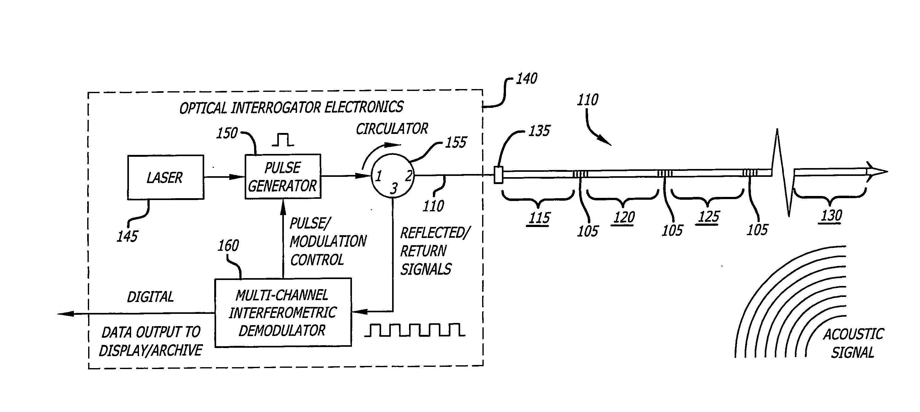
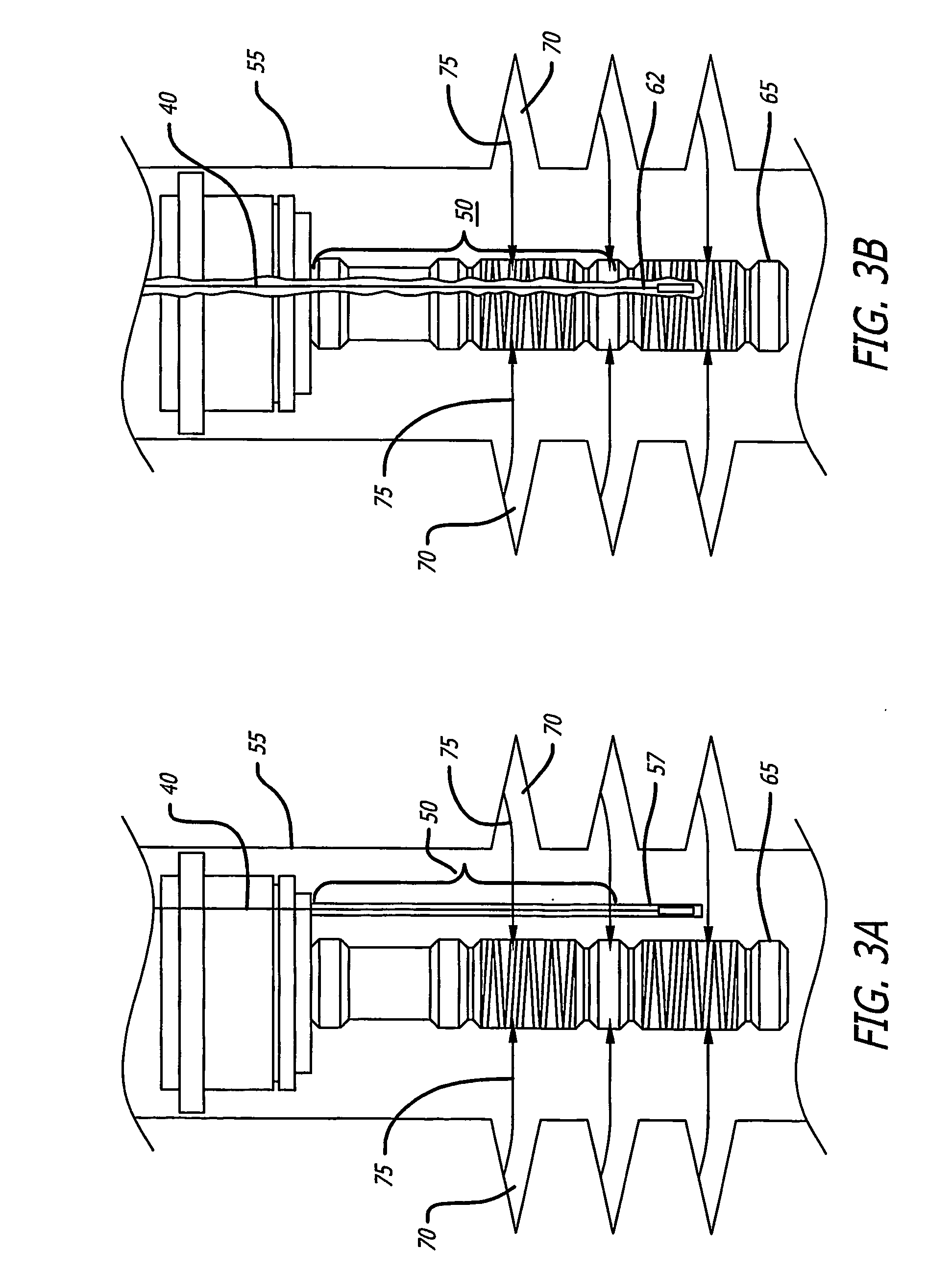
[0014] In one aspect, the present invention is embodied in a fiber optic acoustic sensor that is capable of operating reliably in the harsh environment of a well bore. The ruggedness and reliability is due in part to the simplicity of the sensor, and in part to the sensor design which allows for the location of expensive, delicate and difficult to repair electronic equipment for analyzing signals from the sensor representing received acoustic signals at the well head surface.

Problems solved by technology

The ruggedness and reliability is due in part to the simplicity of the sensor, and in part to the sensor design which allows for the location of expensive, delicate and difficult to repair electronic equipment for analyzing signals from the sensor representing received acoustic signals at the well head surface.
When an acoustic signal impinges upon a sensor section, the acoustic signal causes strain in the optical fiber.
The strain causes the optical path length of the fiber in the interferometer to change, thereby causing a phase change in the light.
This phase change results in a change in the optical intensity of the light returned to the electronic equipment located at the well head.

Method used


Image

  • Downhole fiber optic acoustic sand detector
  • Downhole fiber optic acoustic sand detector
  • Downhole fiber optic acoustic sand detector

Examples


Embodiment Construction

[0030] In its broadest aspect, the present invention is embodied in a system utilizing an optical fiber having one or more fiber Bragg grating sensors formed therein for detecting acoustic signals. The present invention is particularly useful for detecting acoustic signals originating in well holes, and thus provides a means for detecting changes in the acoustic profile of the well caused by the invasion of sand into the well bore.

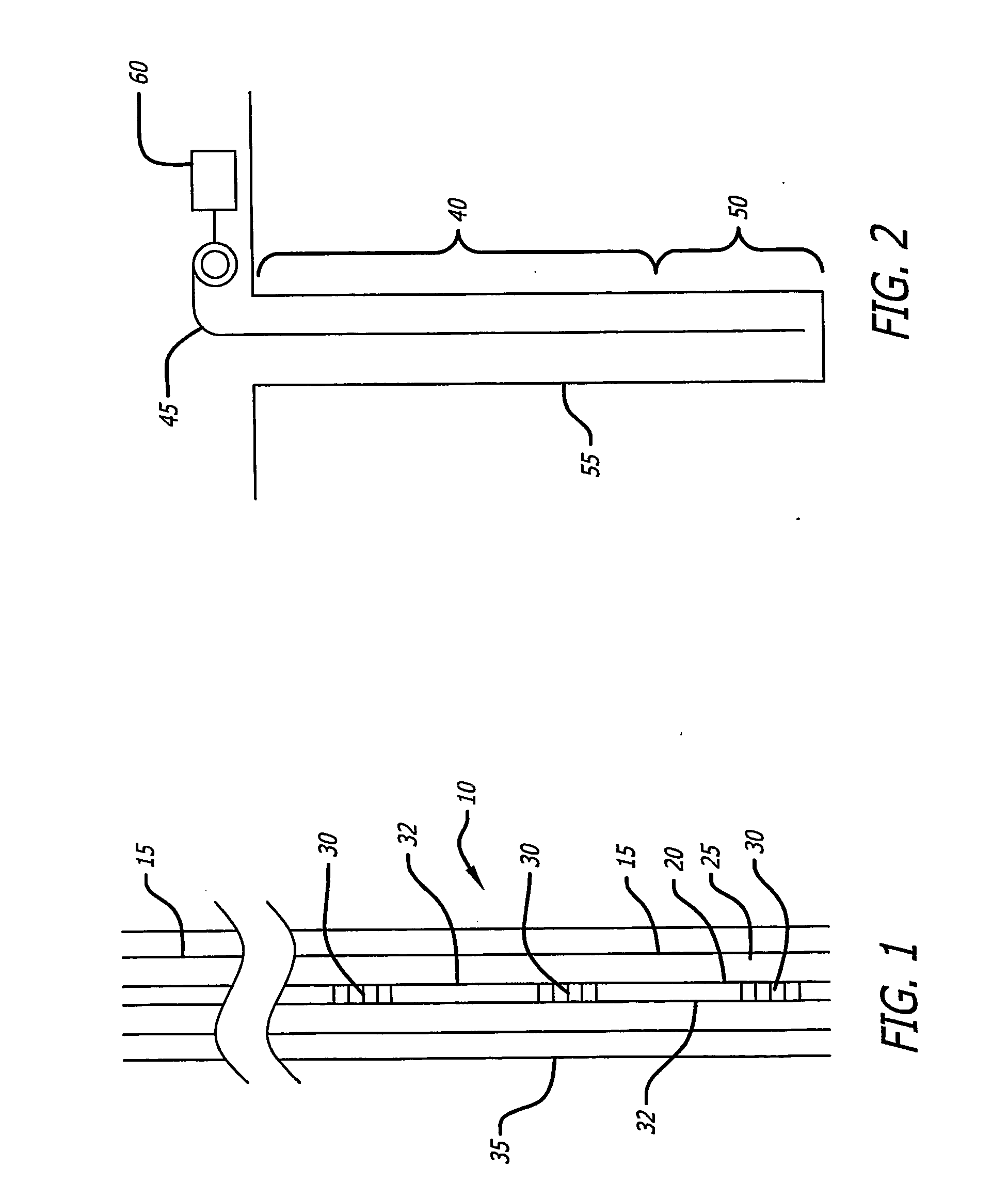
[0031] In one embodiment of the present invention, the optical fiber includes an array of sections of the optical fiber with each section of optical fiber being separated by fiber gratings having a selective reflectivity at predetermined wavelength. In this manner, the an array of acoustic sensors is provided with each segment of the array sensitive to acoustic energy, In this embodiment, each of the segments of the array may be used to detect sand invasion over a segment, or zone, of the well. One advantage of the design of the present invention is that ...


PUM


Abstract

An array of fiber optic acoustic sensors is formed within an optical fiber. The array of acoustic sensors may be deployed to a well bore for detecting acoustic signals occurring within the production area of the well bore, such as acoustic signals resulting from sand invading the well bore. A plurality of acoustic sensors may be formed by forming a plurality of periodic refractive index perturbations at selected intervals within the acoustic sensing section of the optical fiber. The optical fiber may be deployed within the well head within a suitable protective arrangement such as deployed through a tube or armor using a suitable material such that the optical fiber is protected, yet retains sensitivity to acoustic signals. The fiber optic acoustic sensor of the present invention may be unobtrusively mounted on the exterior of a well casing such that the sensor is not in the fluid stream.

Description

CROSS-REFERENCES TO RELATED APPLICATIONS [0001] This application claims the benefit of priority to U.S. Provisional Application No. 60 / 508,383, filed Oct. 3, 2003, the subject matter of which is being incorporated herein in its entirety.FIELD OF THE INVENTION [0002] The present invention relates generally to a system and method for sensing the invasion of an oil or gas well by sand suspended in the fluid or gas being pumped from the well. More specifically, the present invention relates to a rugged and unobtrusive acoustic sensor incorporating one or more acoustic sensing regions which may include one or more hydrophones formed using lengths of optical fibers separated by fiber Bragg gratings that act as partially reflective mirrors to separate the acoustic sensing regions. One or more acoustic sensing sections may be attached to a lead cable and lowered deeply into the well bore. The acoustic sensing regions, or hydrophones, are connected to the surface by the fiber optic cable tha...

Claims


Application Information

Patent Timeline
IPC IPC(8): G02B6/00E21BE21B47/10G01B11/16G01J1/04G02B6/34
CPCG02B6/2932E21B47/101E21B47/107
Inventor GOLDNER, ERIC L.
Owner SABEUS PHOTONICS
Learn More