
System for treating chronic total occlusion caused by lower extremity arterial disease

a total occlusion, chronic disease technology, applied in the direction of catheters, surgery, other medical devices, etc., can solve the problems of increased risk of gangrene, heart attack, stroke and kidney disease, limited opportunity to treat the lower extremity pad,

Inactive Publication Date: 2007-03-01
SHINTECH
View PDF18 Cites 42 Cited by
  • Summary
  • Abstract
  • Description
  • Claims
  • Application Information

AI Technical Summary

Benefits of technology

The system improves the axial positioning of guide wires, enhancing the chances of successful recanalization by allowing precise alignment and engagement of the guide wire, thereby improving treatment outcomes for CTOs in arterial circulation.

Problems solved by technology

In addition to affecting the arteries of the lower extremities, PAD can affect all the arteries of the arterial system, leading to an increase risk of gangrene, heart attack, stroke and kidney disease.
The opportunity to treat lower extremity PAD is limited by the ability to gain successful guide-wire access through the area of arterial disease.
In diffuse and complex arterial stenosis, however, guide-wire access is more difficult, and most problematic with chronic total occlusions (CTO).
In the known systems, once the guide-wire traverses the CTO in the dissection plane, there is great difficulty and complexity involved in returning the guide-wire to the arterial lumen distal to the CTO.
This difficulty often leads to failure to gain distal arterial luminal position of the wire, resulting in failure to successfully recanalize the area of CTO, leaving open surgical revascularization as the only alternative treatment option.

Method used


Image

  • System for treating chronic total occlusion caused by lower extremity arterial disease
  • System for treating chronic total occlusion caused by lower extremity arterial disease
  • System for treating chronic total occlusion caused by lower extremity arterial disease

Examples


Embodiment Construction

[0034] For the purposes of the discussion below, “proximal” is defined as closer to the heart. Conversely, “distal” is defined as further from the heart. Additionally, the “downstream” direction in an artery is defined as the ordinary direction of blood flow (i.e., away from the heart) within the artery, whereas the “upstream” direction in an artery is defined as being opposite the “downstream” direction therein (i.e., toward the heart).

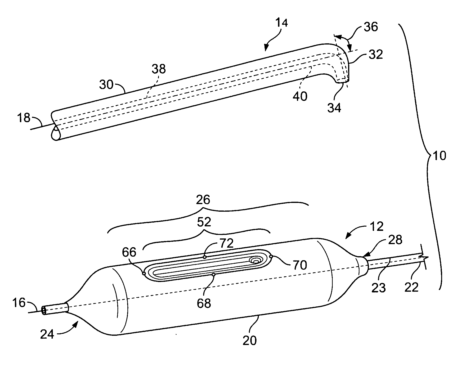
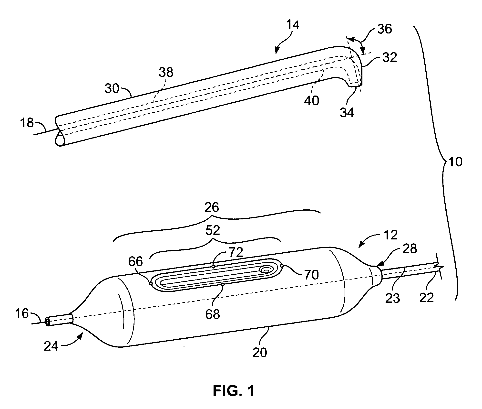
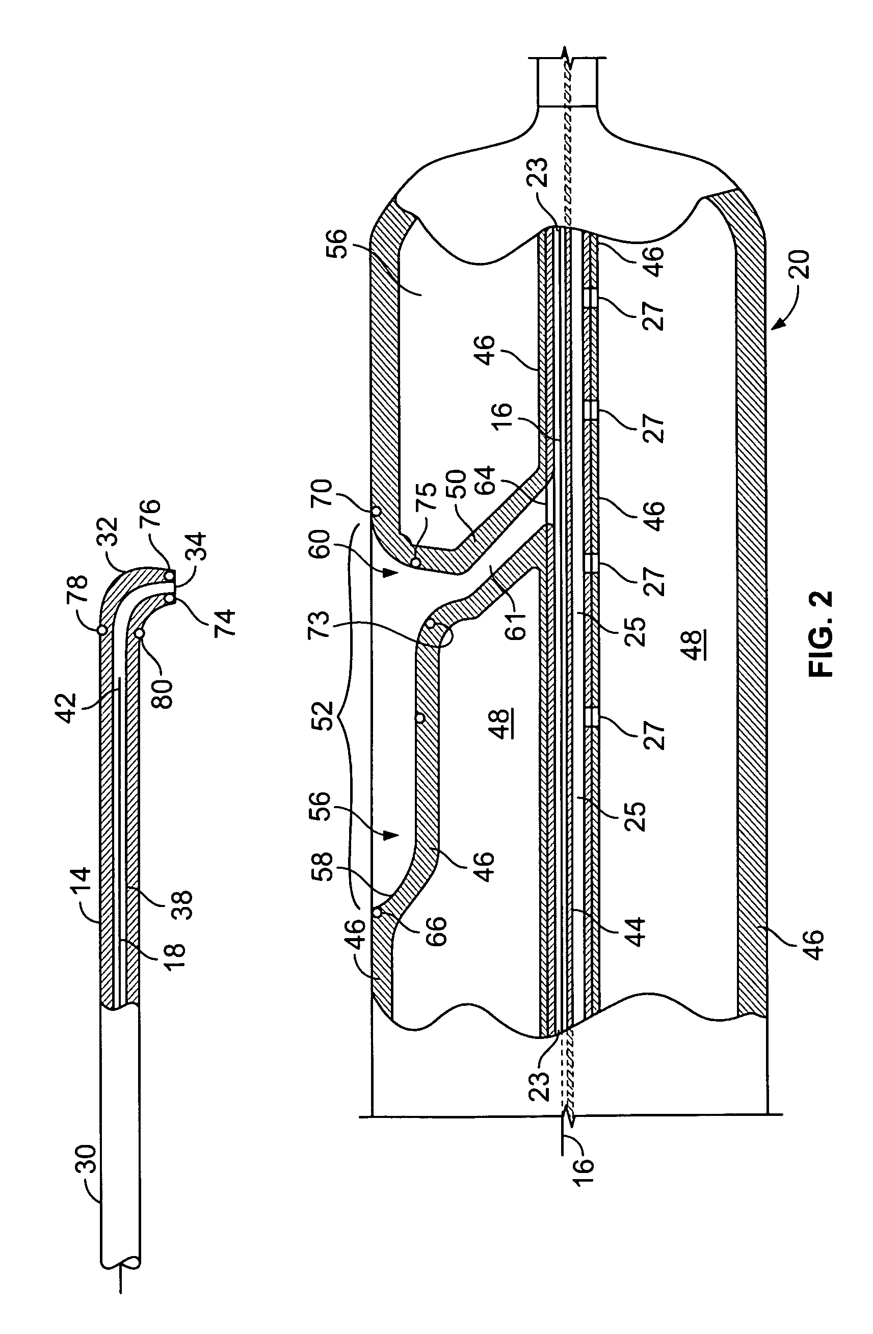
[0035]FIG. 1 is a perspective view of a system 10 for treating patients suffering from chronic total occlusion (hereinafter “CTO”) occurring in the lower extremities, in accordance with a first embodiment of the present invention. The system 10, which may be used in conjunction with the inventive methods described hereinbelow, includes a balloon assembly (also referred to herein as “capture catheter”) 12, an angled catheter 14, and first and second guide-wires 16, 18, respectively, both of which are of conventional construction. For purposes of clar...


PUM


Abstract

The present invention relates to a catheter system useful in treating lower extremity arterial chronic total occlusion (CTO). More particularly, the catheter system includes a first catheter having a first lumen extending therethrough, and a second catheter having a second lumen extending therethrough. The second catheter includes an engaging mechanism, such as an inflatable balloon, for engaging at least a portion of the first catheter such that a guide wire can be fed from the first lumen of the first catheter to the second lumen of the second catheter. In use, the first catheter is advanced to a treatment site through a vascular body from a downstream side of the treatment site. The second catheter is also advanced to the treatment site through the vascular body from an upstream side of the treatment site. The second catheter is engaged with the first catheter within the vascular body. The guide wire is then fed from the first catheter into the second catheter. Thereafter, the first and second catheters are removed from the vascular body, thereby leaving the guide wire extending through the treatment site. The guide wire is used to advance a treatment balloon to the treatment site for treating a CTO condition existing therein.

Description

CROSS-REFERENCE TO RELATED APPLICATION [0001] The present application is a continuation-in-part of U.S. patent application Ser. No. 11 / 197,968 filed Aug. 5, 2005, the entire disclosure of which is incorporated herein by reference in its entirety.FIELD OF THE INVENTION [0002] The present invention relates to dilation type balloon catheters, and diagnostic catheters for use in the treatment of stenotic regions within the arterial circulation. More particularly, the present invention relates to systems and methods for the treatment of chronic total occlusion (CTO) of the arterial circulation occurring in the lower extremities. BACKGROUND OF THE INVENTION [0003] The arterial circulation is a system of tubes, comprised of a wall that defines a channel or lumen therein through which blood flows. In Peripheral Arterial Disease (PAD), the arterial wall becomes thickened and results in a corresponding reduction in the available area of the lumen through which blood flows. This reduction in t...

Claims


Application Information

Patent Timeline
Patent Type & Authority Applications(United States)
IPC IPC(8): A61M29/00
CPCA61M25/1011
Inventor SHINDELMAN, LARRY EARL
Owner SHINTECH
Learn More