Vesicovaginal incontinence device and method of use

a technology of incontinence device and vesicovaginal tube, which is applied in the field of incontinence device, can solve the problems of general leakage through the urethra, significant impact on the mobility of women, and inability to void the bladder at all, so as to prevent backflow

Inactive Publication Date: 2007-03-01
GUTIERREZ J SANTIAGO
View PDF9 Cites 15 Cited by
  • Summary
  • Abstract
  • Description
  • Claims
  • Application Information

AI Technical Summary

Benefits of technology

[0015] The fluid reservoir has an adjustable securing means, preferably a belt, attached to it for securing the fluid reservoir to a user's leg. In addition, the fluid reservoir has an intake tube at one end that is removably connected to the second end of the drainage

Problems solved by technology

This incontinence; however, is generally leakage through the urethra.
The hallmark symptom of all vesicovaginal fistulae is constant urinary drainage into the vaginal vault and a subsequent incontinence due to the vagina's inability to control bladder function.
In fact, if the fistula is large enough, the woman may not be able to void her bladder at all due to the diminished pressure gradient from the drainage.
Without repair, a vesicovaginal fistula can be physically debilitating creating a significant impact on a woman's mobility.
In addition to the physical symptoms, the psychological effects of a vesicovaginal fistula can be disastrous.
The severe incontinence destroys a woman's normal functioning in society.
As a result of familial and social rejection, coupled with humiliation, many women with fistula live for years without any financial or social support since they are unable to make a living by themselves and have been ostracized.
Understandably, some women cannot handle the effects o

Method used


Image

  • Vesicovaginal incontinence device and method of use
  • Vesicovaginal incontinence device and method of use
  • Vesicovaginal incontinence device and method of use

Examples


Embodiment Construction

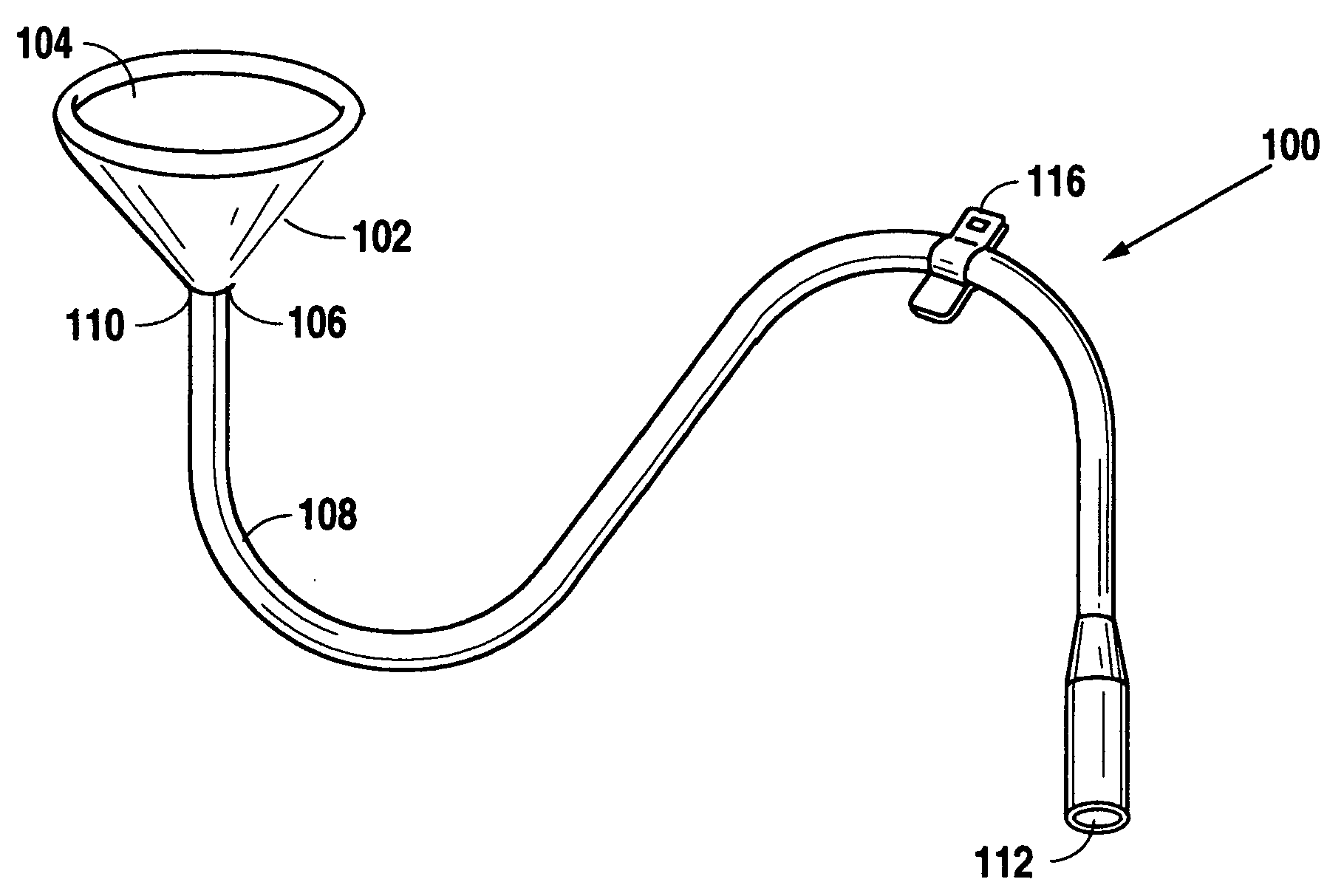
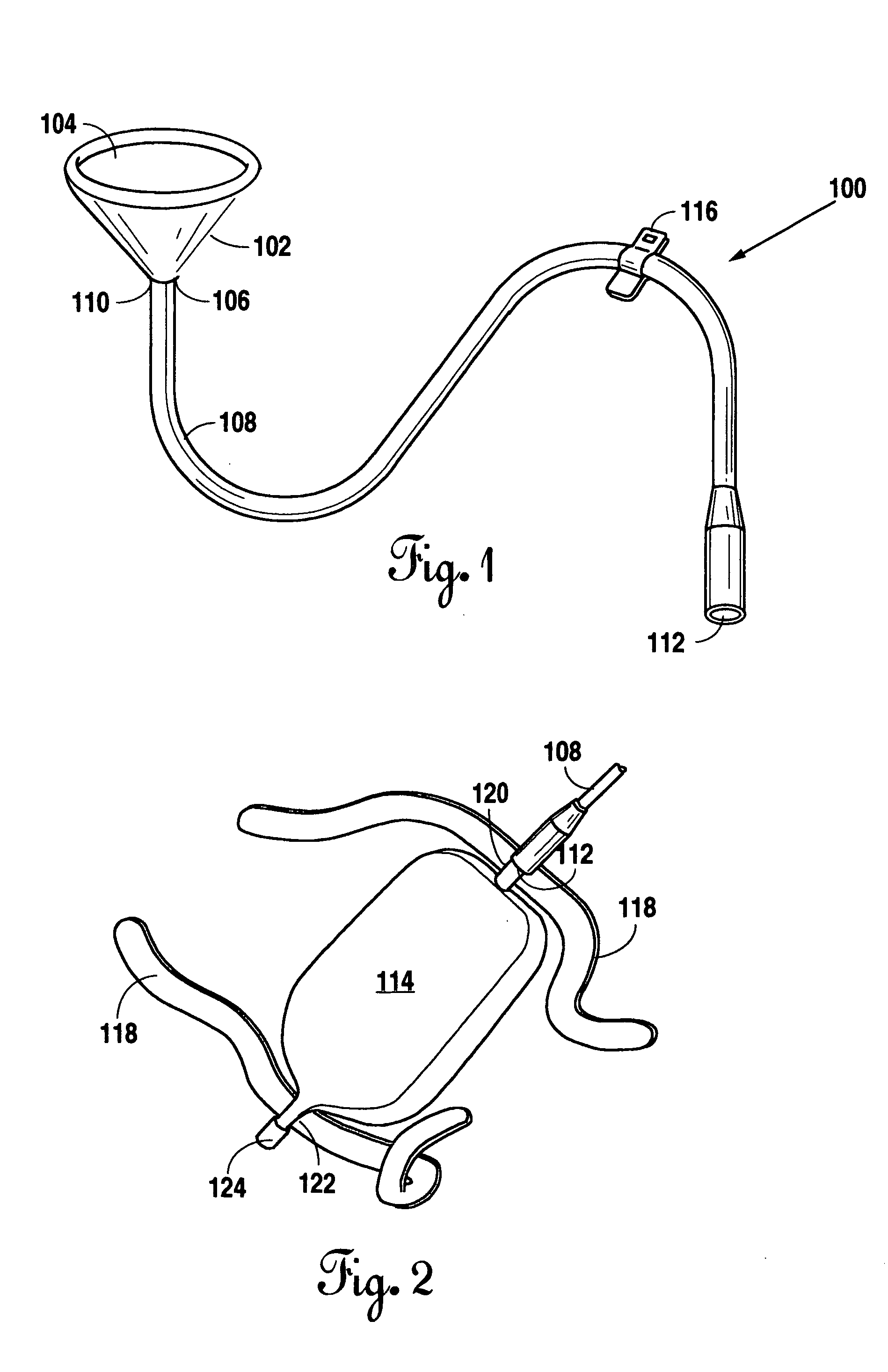
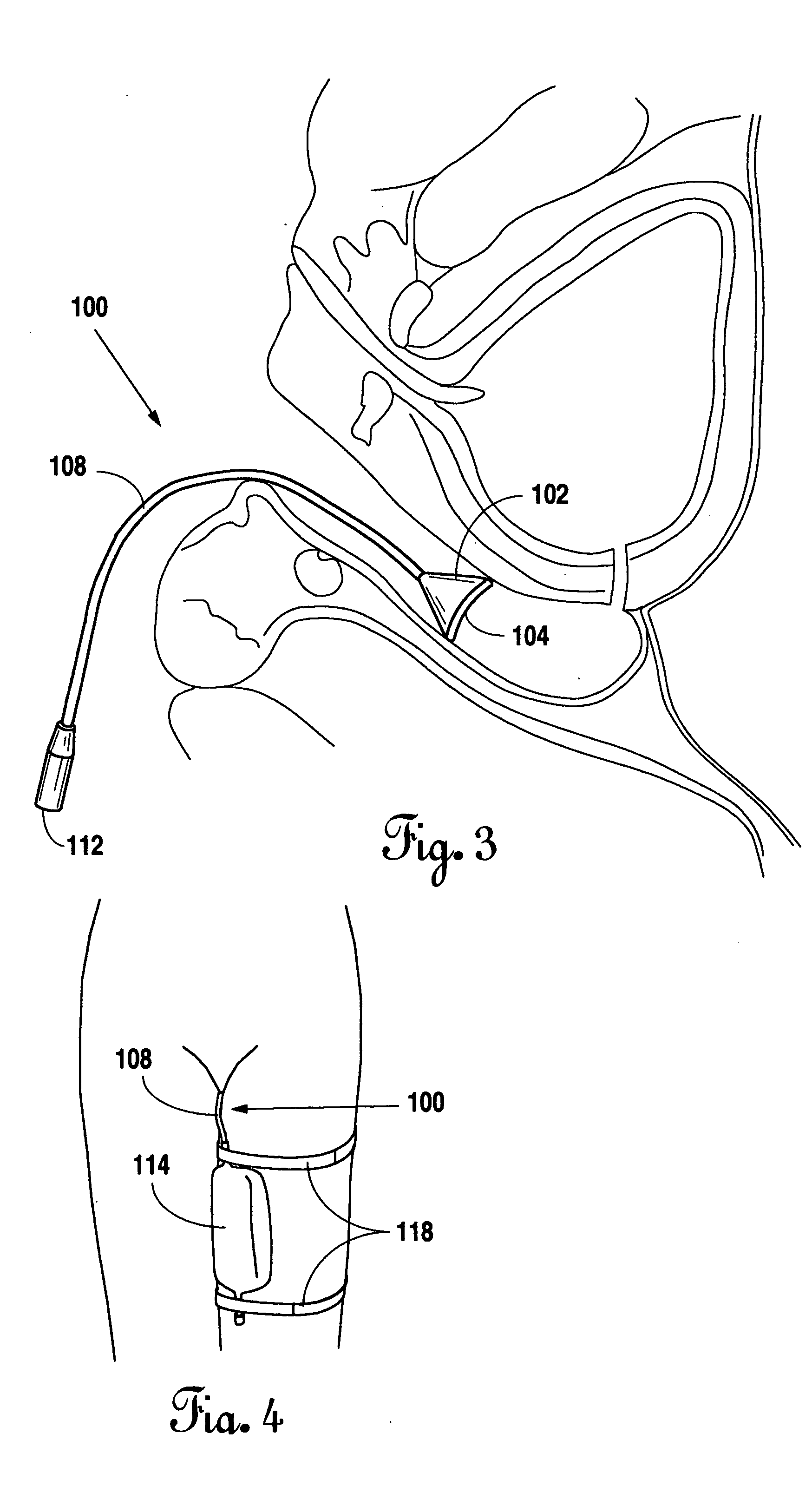
[0021] In FIG. 1, a perspective view of the preferred embodiment 100 of the present invention is shown. A flexible rubber hemispherical funnel 102 is shown having an inlet port 104 and an outlet port 106. A first end 110 of a drainage tube 108 is contiguous with the outlet port 106 of the funnel 102. The drainage tube 108 is preferably medical grade rubber. The second end 112 of the drainage tube 108 is removably connected to a fluid reservoir 114 (See FIG. 2). A clamping means 116 is positioned on the drainage tube 108. The clamping means 116 regulates drainage within the drainage tube 108.

[0022]FIG. 2 shows a perspective view of the fluid reservoir 114 for the preferred embodiment of the present invention. The fluid reservoir 114 has an adjustable securing means 118, preferably a belt, attached to it for securing the fluid reservoir 114 to the user's leg. The fluid reservoir 114 is preferably soft and light weight with a non-woven backing to allow the skin to breathe and feel com...


PUM


Abstract

A vesicovaginal incontinence device having a flexible rubber hemispherical funnel with an inlet port and an outlet port. A first end of a rubber drainage tube is contiguous with the outlet port. The second end of the rubber drainage tube is removably connected to a fluid reservoir. A clamping means is positioned on the drainage tube for regulating drainage within the drainage tube. The fluid reservoir has a securing means attached to it for securing the fluid reservoir to a user's leg. The fluid reservoir has an intake tube at one end that is removably connected to the second end of the drainage tube. This intake tube has a non-return valve contained within it to prevent backflow. The fluid reservoir also contains an outlet tube at its lowermost end for draining fluid from the reservoir. The outlet tube has a one way valve for releasing urine from the reservoir.

Description

BACKGROUND OF THE INVENTION [0001] 1. Field of the Invention [0002] Applicant's invention relates to a vesicovaginal incontinence device. More specifically, the present invention relates to a vesicovaginal incontinence device for collection of urine from the vagina due to incontinence from a vesicovaginal fistula. [0003] 2. Background Information [0004] In a healthy female, the urinary system removes urea from the blood. Urea is carried in the bloodstream to the kidneys. The kidneys remove urea from the blood through filtering units called nephrons. Each nephron consists of a ball of small blood capillaries called the glomerulus and a small tube called a renal tube. Urea, together with water and other waste substances, forms the urine as it passes through the nephrons and down the renal tubes of the kidney. From the kidneys, urine travels down two tubes called ureters to the bladder. Circular muscles in the bladder called sphincters keep the urine from leaking. When the sphincter mu...

Claims


Application Information

Patent Timeline
IPC IPC(8): A61F5/44
CPCA61F5/4553A61F5/4405
Inventor GUTIERREZ, J. SANTIAGO
Owner GUTIERREZ J SANTIAGO
Why Eureka
Try Eureka