Devices and methods for treatment of vascular aneurysms

a technology for vascular aneurysms and devices, applied in the field of devices and methods for the treatment of aneurysms found in blood vessels, can solve the problems of high the sponge filler material acts like a graft, and the acute success rate of these devices is very high, so as to prevent the migration of the graft and promote cellular ingrowth. , the effect of minimizing the volume of the material

Active Publication Date: 2007-03-01
ENDOLOGIX LLC
View PDF97 Cites 80 Cited by
  • Summary
  • Abstract
  • Description
  • Claims
  • Application Information

AI Technical Summary

Benefits of technology

[0005] In a first aspect, the present invention provides a two part prostheses where one part is an expandable sponge structure and the other part is an expandable tubular mesh structure. The expandable sponge structure is intended to fill the aneurysm cavity to prevent further dilatation of the vessel wall by creating a buffer or barrier between the pressurized pulsating blood flow and the thinning vessel wall. The expandable tubular mesh structure, which is placed across the aneurysm contacting the inner wall of healthy vessel proximal and distal to the aneurysm, serves two purposes. One, it defines the newly formed vessel lumen, even though it does not by itself provide a fluid barrier between the blood flow and the aneurysm. Two, it keeps the expandable sponge structure from protruding out of the aneurysm and into the newly formed vessel lumen. The expandable tubular mesh structure is delivered first across the aneurysm. Then, the expandable sponge structure is delivered via a catheter-based delivery system through a “cell” of the tubular mesh structure and into the aneurysm sac. When the sponge structure is deployed into the aneurysm sac and comes in contact with fluid, it will expand to a size larger than the largest opening or cell of the tubular mesh structure as to prevent the sponge structure from getting out of the aneurysm sac. The filled aneurysm sac will most likely clot off and prevent further dilation of the aneurysm and subsequent rupture. The blood flow should maintain a natural lumen where the luminal diameter is approximately defined by the diameter of the tubular mesh structure. The advantage of this system is that the sponge filler material acts like a graft but has unparalleled durability. The metallic structure can be optimized for durability as well because the size constraint is somewhat relieved due to the absence of an integrated graft material, which takes up a significant amount of space in a catheter.
[0007] In another aspect, the present invention provides an inflatable tubular balloon graft. It is a tubular graft, straight or bifurcated, where its wall is not a solid structure but a hollow chamber. The chamber can be filled with a variety of materials which can dictate the mechanical properties of the prostheses. The unfilled tubular balloon graft can be folded and loaded into a catheter-based delivery system, and once in position the tubular balloon graft can be “inflated” with the filler material. The material would be filled in a fluid form and may stay a fluid form or can be solidified by various means such as UV light, heat, and time. The advantage of this system is that a metallic structure is not needed to provide structure to the graft. It is instead replaced by the injectable fluid within the chamber of the tubular balloon graft. Customization of the mechanical properties of the graft is easily accomplished by using balloon fillers of varying properties.
[0008] The tubular balloon graft can be completely non-porous, completely porous with same degree of porosity throughout the graft, completely porous with varying porosity within the graft, or partially non-porous and partially porous. Significant porosity on the very outer layer would allow for delivery of an aneurysm sac filling substance or a drug. Porosity on the ends of the graft will help promote cellular in-growth. Porosity on the ends can also be used to deliver an adhesive so that the graft can be securely attached to the vessel wall.
[0009] Another embodiment of the tubular balloon graft includes a tubular balloon graft with a bulging outer layer. This will allow the outer surface of the tubular balloon graft to fill some or all of the aneurysm. This will provide a primary or secondary barrier for the aneurysm wall from the pulsating blood flow and will provide a means to prevent migration of the graft due to the enlarged area within the graft. An alternate method of construction would be to attach a bulging outer skin to a standard tubular thin-walled graft and provide a port for injection of the filler substance. Alternatively, instead of a bulging outer skin, a very compliant outer skin can be used so that the volume of material is minimized. The compliant outer skin would be able to expand at very low inflation pressures that would be non-destructive to the aneurysm wall.

Problems solved by technology

One, it defines the newly formed vessel lumen, even though it does not by itself provide a fluid barrier between the blood flow and the aneurysm.
The advantage of this system is that the sponge filler material acts like a graft but has unparalleled durability.
The acute success rate of these devices is very high, but there are a significant number of these which develop leaks, or blood flow / pressure re-entering the aneurysm sac, some time after the procedure.

Method used


Image

  • Devices and methods for treatment of vascular aneurysms
  • Devices and methods for treatment of vascular aneurysms
  • Devices and methods for treatment of vascular aneurysms

Examples


Embodiment Construction

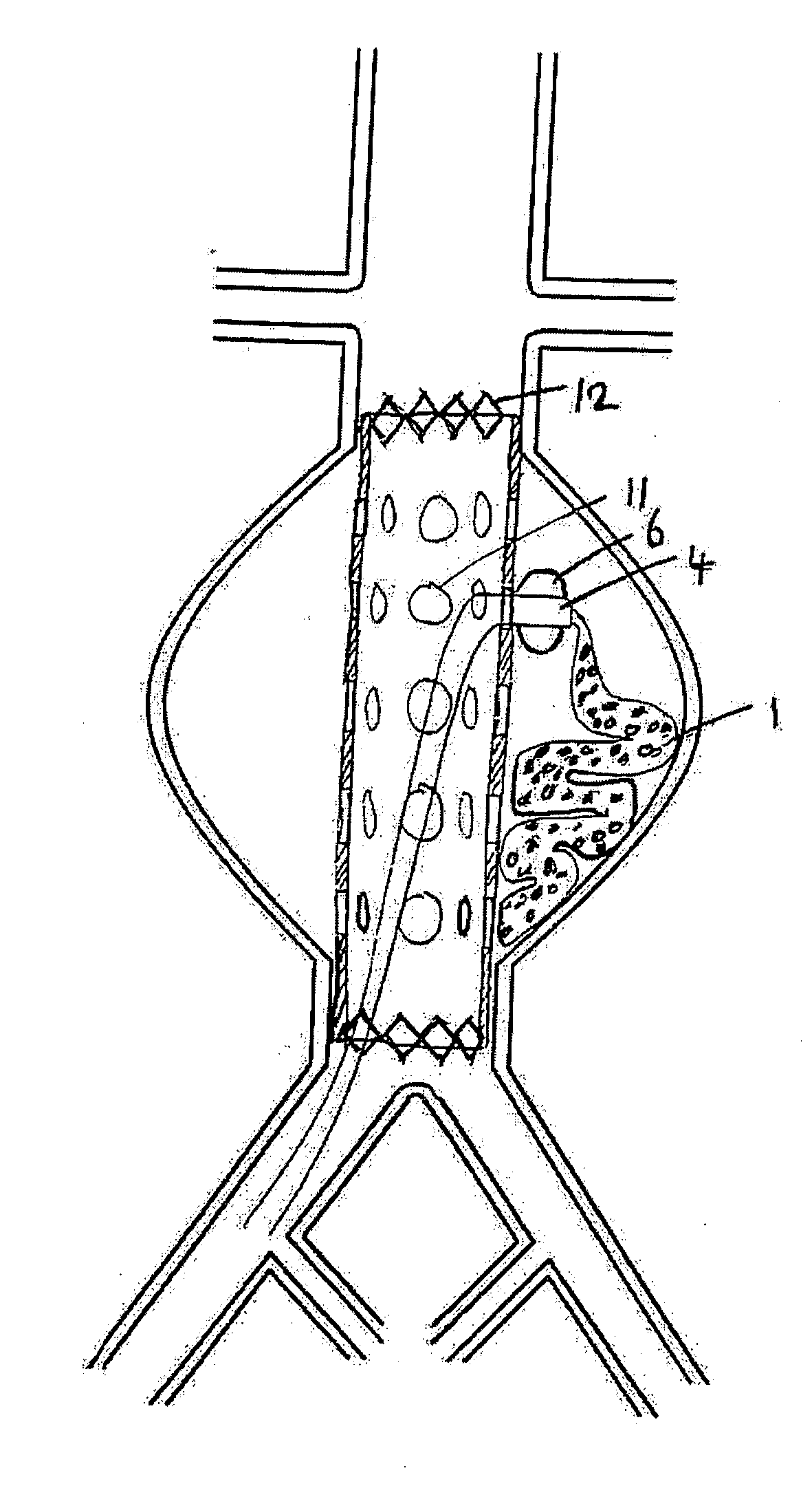
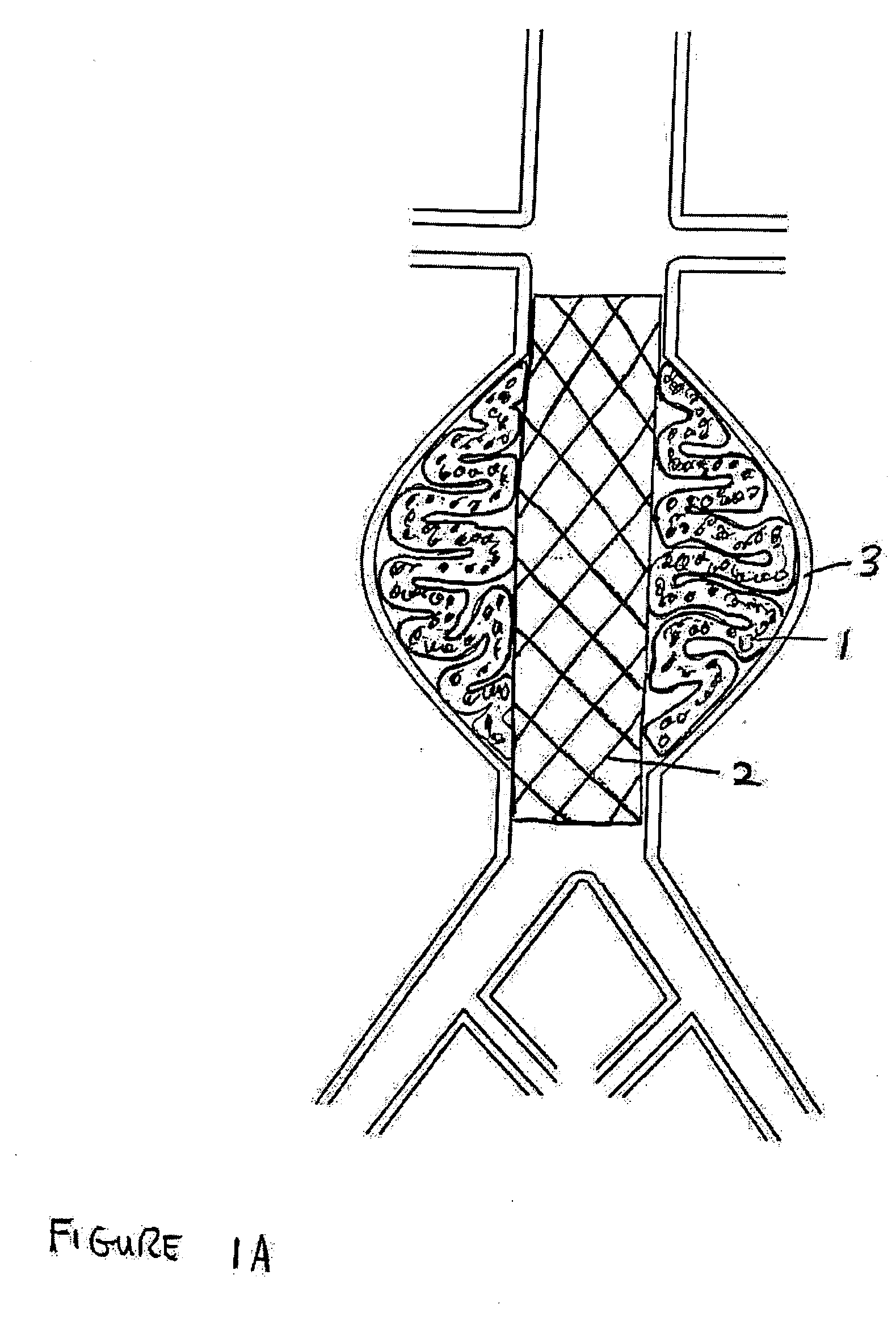
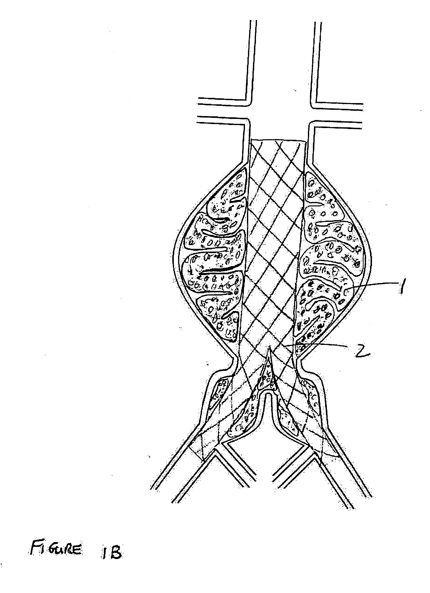
[0029]FIG. 1A shows the two-part prosthesis comprising of an expandable sponge structure 1 and an expandable tubular mesh structure 2 placed in an abdominal aortic aneurysm 3 located in the infra-renal aorta not involving the iliac arteries. FIG. 1B shows a bifurcated version of the expandable tubular mesh structure 2 and the expandable sponge structure 1 in an abdominal aortic aneurysm located in the infra-renal aorta and involving both iliac arteries. FIG. 1C shows an expandable tubular mesh structure 2 placed across an aneurysm commonly found in cerebral arteries and the expandable sponge structure 1 filling up the aneurysm. The expandable sponge structure 1 is placed through the expandable tubular mesh structure 2 into the aneurysm, filling up the aneurysmal sac which provides a barrier between the thin fragile wall of the aneurysm and the pressurized pulsating blood. The tubular mesh structure 2 keeps the expanded sponge 1 within the confines of the aneurysm and away from the f...


PUM


Abstract

The present invention relates to devices and methods for the treatment of diseases in the vasculature, and more specifically, devices and methods for treatment of aneurysms found in blood vessels. In a first embodiment of the present invention, a two part prostheses, where one part is an expandable sponge structure and the other part is an expandable tubular mesh structure, is provided. In the first embodiment, the expandable sponge structure is intended to fill the aneurysm cavity to prevent further dilatation of the vessel wall by creating a buffer or barrier between the pressurized pulsating blood flow and the thinning vessel wall. In the first embodiment, the expandable tubular mesh structure is placed across the aneurysm, contacting the inner wall of healthy vessel proximal and distal to the aneurysm.

Description

CROSS-REFERENCE TO RELATED APPLICATION [0001] This application is a continuation of and claims the benefit of U.S. patent application Ser. No. 10 / 301,061, filed Nov. 20, 2002, which claims the benefit of U.S. Provisional Application No. 60 / 333,373, filed Nov. 26, 2001, which are incorporated herein by reference in their entireties.BACKGROUND OF THE INVENTION [0002] The present invention relates to devices and methods for the treatment of diseases in the vasculature, and more specifically, devices and methods for treatment of aneurysms found in blood vessels. Aneurysms can occur in various areas of the cardiovascular system, but are commonly found in the abdominal aorta, thoracic aorta, and cerebral vessels. Aneurysms are unusual ballooning of the vessel due to loss of strength and / or elasticity of the vessel wall. With the constant pulsating pressure exerted on the vessel wall, the diseased or weakened wall can expand out and potentially rupture, which frequently leads to fatality. ...

Claims


Application Information

Patent Timeline
Patent Type & Authority Applications(United States)
IPC IPC(8): A61F2/94A61BA61B17/12A61B17/34A61M25/12
CPCA61B17/12022A61F2/954A61B17/12136A61B17/12186A61B17/1219A61B17/12195A61B2017/00898A61B2017/00986A61B2017/1205A61B2017/3484A61F2/958A61F2/07A61F2002/065A61F2002/077A61F2002/823A61F2/90A61B17/12118A61F2250/0003A61B17/12036
Inventor KIM, STEVEN W.SHIU, BRIAN K.HOLMGREN, NEIL
Owner ENDOLOGIX LLC
Why Eureka
Try Eureka