Storage system, storage device, and control method thereof

Inactive Publication Date: 2007-03-01
HITACHI LTD
View PDF4 Cites 135 Cited by
  • Summary
  • Abstract
  • Description
  • Claims
  • Application Information

AI Technical Summary

Benefits of technology

[0014] In the storage system of the present invention, the power consumption is low, the installation area is small, and it is possible to construct a large-scale system. Also, it is possible to provide a high system performance in accordance with the medium for stor

Problems solved by technology

On the other hand, demand for recording data reliably for a long period of time is increasing.
However, in general, in a large-scale storage system using hard-disk drives (in the following, referred to as “HDDs”), the amount of power consumption increases in proportion to the storage capacity.
That is to say, the possession of a storage system with a large capacity means an increase in the total cost of ow

Method used


Image

  • Storage system, storage device, and control method thereof
  • Storage system, storage device, and control method thereof
  • Storage system, storage device, and control method thereof

Examples


Example

First Embodiment

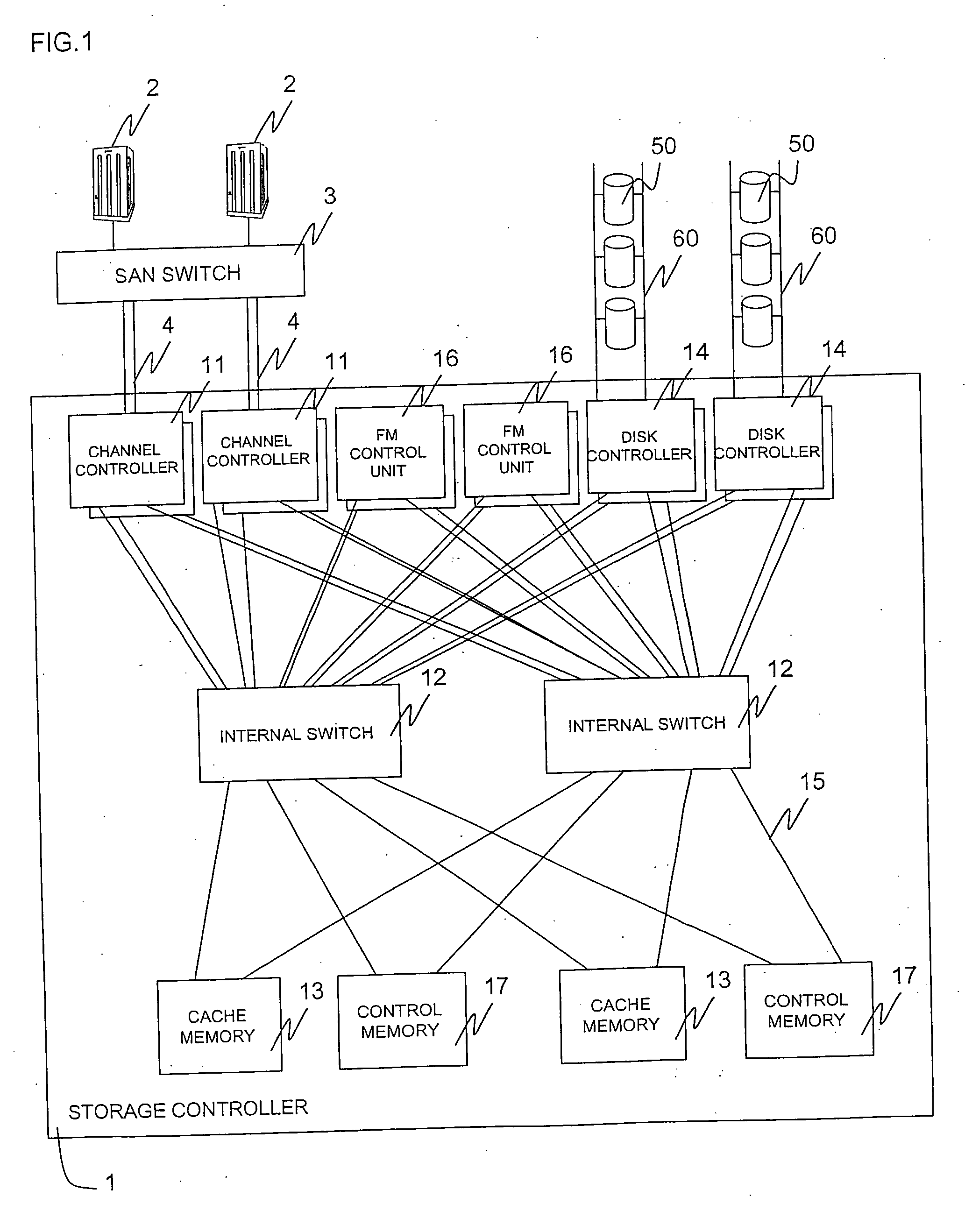
[0035] A description will be given of a first embodiment. FIG. 1 is a block diagram of a configuration of a storage system according to the first embodiment of the present invention. The storage system includes a storage controller 1, hard disk drives (HDDs) 50, and a flash memory device (in the figure, an example of an FM control unit 16 internally including flash memory devices is shown). The storage controller 1 is connected to a host computer 2 via a channel 4 through a SAN (Storage Area Network) including a SAN switch 3. Also, the storage controller 1 is connected to a plurality of HDDs 50 which are media storing data through a disk-side channel 60. The storage controller 1 includes a plurality of channel controllers 11, a plurality of cache memories 13, a control memory 17, a plurality of disk controllers 14, a plurality of FM control units 16, and internal switches 12 connecting these through an internal bus 15. The channel controller 11 receives an input / out...

Example

Second Embodiment

[0056] A description will be given of a second embodiment. FIG. 13 is a block diagram of a storage system according to the second embodiment of the present invention. In this embodiment, the FM control unit is implemented at the position equal to the cache memory 13 and the control memory 15. In general, the cache memory 13 and the control memory 15 may not be implemented at the position where the channel 4 and the disk-side channel 60 can be connected unlike the channel controller 11 and the disk controller 14. There is no restriction on the implementation, for example, there is no need for disposing the cache memory 13 and the control memory 15 at the front surface of the device for easy work of connecting to the channel 4, and there is no need for disposing near the HDD 50 by the restriction of the transmission path of the disk-side channel 60. Accordingly, it is possible to implement the memories more compactly by disposing the memories at this position. In thi...


PUM


Abstract

A storage system including a storage device 1 which includes: media 50 for storing data from a host computer 2; a medium controller 14 for controlling the media; a plurality of channel controllers 11 for connecting to the host computer 2 through a channel; and a cache memory 13 for temporarily storing data from the host computer 2, wherein the media 50 have a restriction on a number of writing times. The storage device 1 includes a bus 123 for directly transferring data from the medium controller 14 to the channel controller 11.

Description

[0001] The present application is based on and claims priority of Japanese patent applications No. 2005-252989 filed on Sep. 1, 2005, the entire contents of which are hereby incorporated by reference. BACKGROUND OF THE INVENTION [0002] 1. Field of the Invention [0003] The present invention relates to a storage device and the control method thereof. [0004] 2. Description of the Related Art [0005] In recent years, the reduction of the total cost of ownership (TCO) of a storage system becomes increasingly important in information business sites such as a data center. On the other hand, demand for recording data reliably for a long period of time is increasing. As an example of this fact, the document data of financial institutions, medical institutions, etc., are required to be stored without being erased by law. Under these circumstances, there is much demand for highly reliable storage systems having a large capacity. However, in general, in a large-scale storage system using hard-di...

Claims


Application Information

Patent Timeline
IPC IPC(8): G06F13/00G06F12/14
CPCG06F3/0626G06F3/0658G06F3/067G06F3/0688G06F12/0246G06F2212/2022G06F2212/263G06F2212/314Y02B60/1225G06F12/0866Y02D10/00G06F3/061G06F3/0649G06F3/0685G06F3/0689G06F12/0802G06F2212/1044G06F2212/60G06F2212/7211G11C16/10G11C16/26
Inventor NAKAMURA, SHUJIFUJIMOTO, KAZUHISAFUJIBAYASHI, AKIRA
Owner HITACHI LTD
Why Eureka
Try Eureka