Electrohydrodynamic evaporator device

a technology of electrohydrodynamic and evaporator, which is applied in the direction of refrigeration and liquid storage, lighting and heating equipment, refrigeration machines, etc., can solve the problems of increasing passive thermal exchange efficiency, limited heat exchange effect, and prolonging process time, so as to reduce reduce the volume and weight. , the effect of reducing the amount of refrigeran

Inactive Publication Date: 2007-03-08
NAT TAIPEI UNIV OF TECH
View PDF11 Cites 4 Cited by
  • Summary
  • Abstract
  • Description
  • Claims
  • Application Information

AI Technical Summary

Benefits of technology

[0010] The present invention further provides an EHD evaporator device having a reduced dimension, volume and weight.
[0011] Moreover, the present invention provides an EHD evaporator device having a reduced amount of refrigerant required therefore.
[0012] The EHD evaporator device according to the present invention comprises an evaporators which has one or more electrodes, the evaporator is a case having a plurality of openings thereon and one or more metal tubes therein each being filled with a working fluid, one or more insulation seats disposed at a refrigerant inlet / outlet or a refrigerant transition so as to avoid electric arc caused by a high voltage when an insufficient insulation is existed between electrodes from occurring, an insulated support member used to fix an electrode and isolate the electrode and metal tube, a voltage applicable insulator comprising a voltage applicable insulator and a voltage applicable insulator and inputtable by a high voltage and one or more electrodes disposed in the working fluid and capable of generating an electric field, wherein the working fluid is filled in the metal tube of the evaporator and the electrode is disposed in the working fluid and fixed with the insulated support member and connected to the insulation seat of the voltage applicable insulator at one end, the voltage applicable insulator being installed at an opening of the evaporator case so as to be connected to a high voltage power supplying device.

Problems solved by technology

However, this manner may only increase the thermal exchange efficiency passively with results of limited heat exchange effect, prolonged process time and larger volume and weight of the evaporator.
Only a passive improvement in structure is provided and the heat exchange efficiency may not be self-controlled.
Since the evaporator may only be improved in structure, dimension, volume and weight of the evaporator may not be efficiently reduced.

Method used


Image

  • Electrohydrodynamic evaporator device
  • Electrohydrodynamic evaporator device
  • Electrohydrodynamic evaporator device

Examples


Embodiment Construction

[0020] The present invention discloses an electrohydrodynamic (EHD) evaporator device and will be described below with one used in a refrigerant R-22 iced water system as an example.

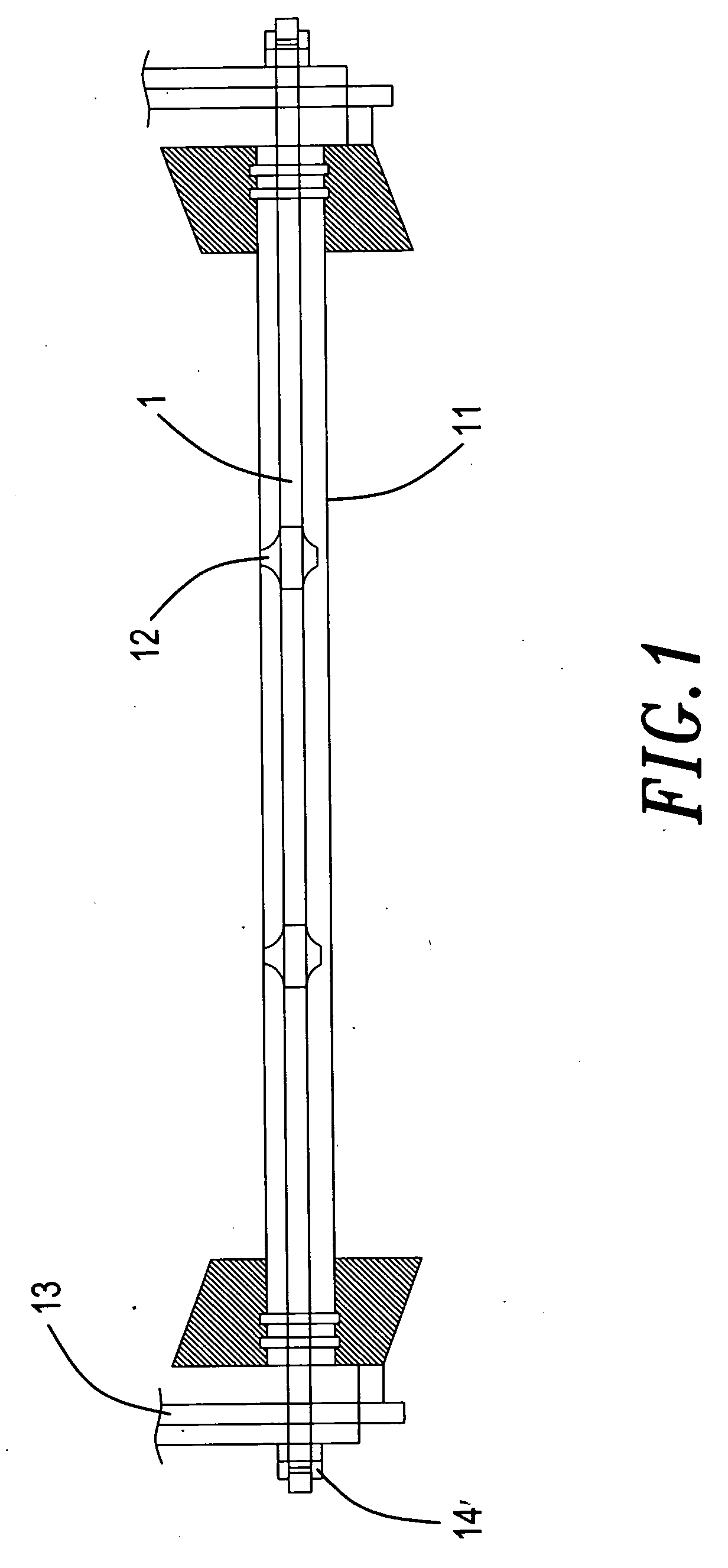
[0021] Referring to FIG. 1, a schematic diagram of the EHD evaporator device according to the present invention is shown therein. In the EHD evaporator device, an electrode 1 is disposed in a copper tube 11 having an inner wall manufactured in a macro-fin form. An insulated support element 12 is provided to fix the electrode 1 at a specific position in relation to the copper tube 11, so that the electrode 1 (served as a positive electrode) and the copper tube 11 (served as a negative electrode) may be exempted from contact with each other. In addition, an insulation seat 13 is provided at each end of the electrode 1 and the copper tube 11 for fixation thereof.

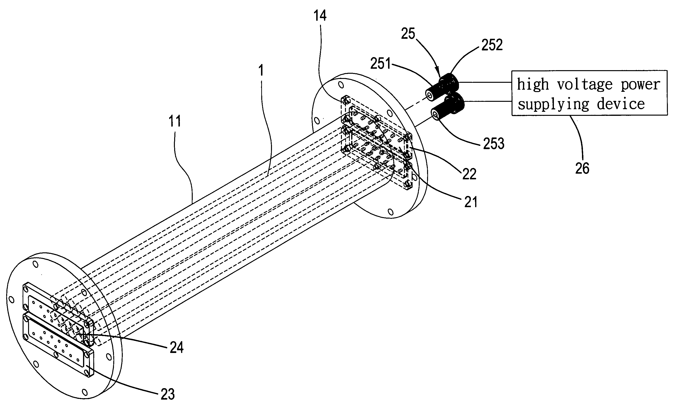
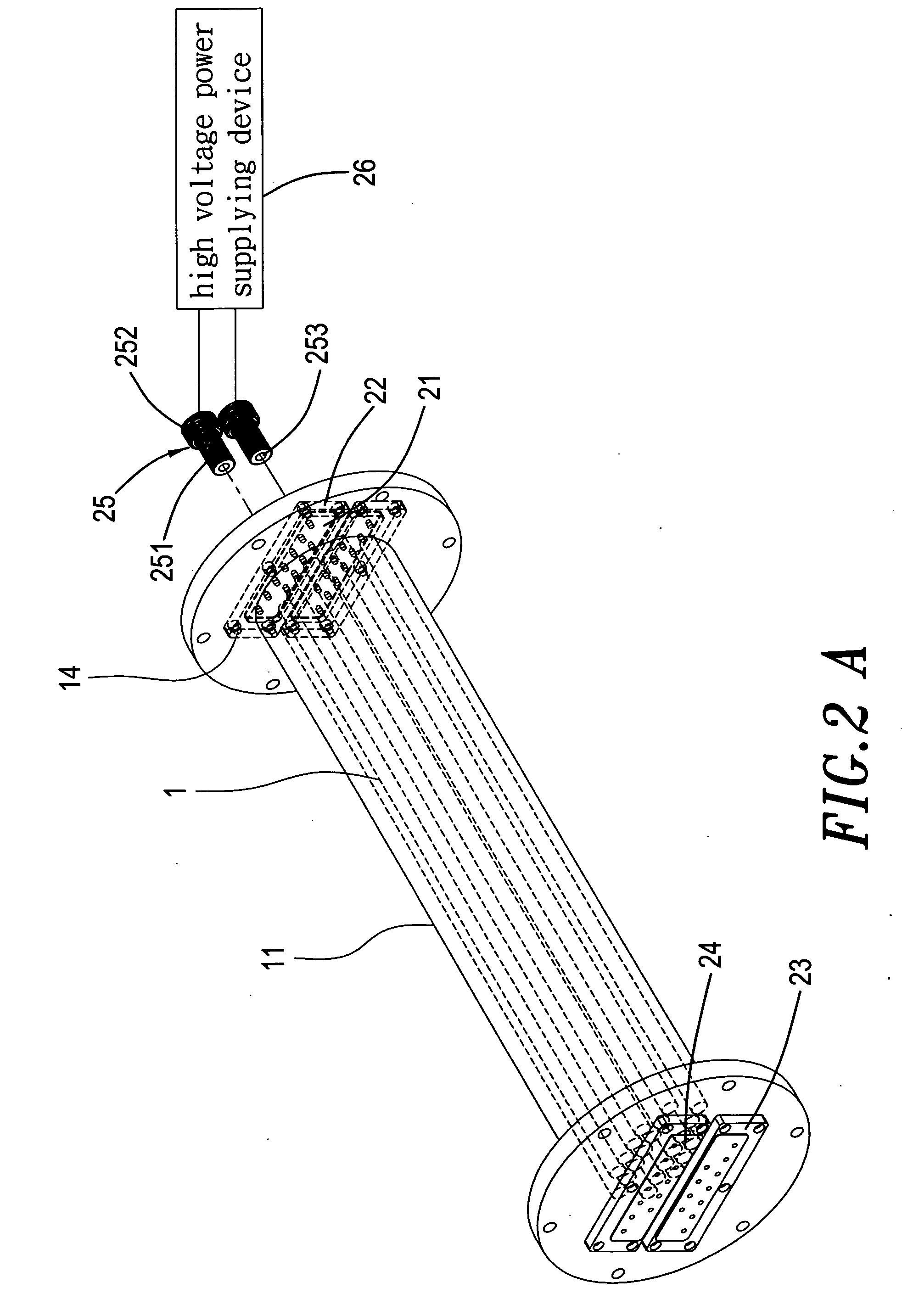
[0022] Referring to FIG. 2A, a perspective view of the EHD evaporator device according to the present invention is shown therein. The EHD evapora...


PUM


Abstract

An electrohydrodynamic evaporator device (EHD) has an EHD electrode. An electric field is generated upon a fluid of low conductivity inside the evaporator device and an enhanced thermal transport effect is then achieved since a thermal boundary layer near a thermal transport surface is caused to have a greater perturbation while a very small voltage drop. With the EHD utilized, size, weight, cost and required refrigerant amount of the evaporator device are reduced. Further, thermal transport efficiency of the alternative refrigerant is improved, making the EHD evaporator device in compliance with associated refrigerant regulations made by CFC and achieve the purposes of environmental protection and energy saving.

Description

BACKGROUND OF THE INVENTION [0001] 1. Field of the Invention [0002] The present invention pertains to an electrohydrodynamic (EHD) evaporator device, and particularly to an electrohydrodynamic evaporator device having an enhanced thermal transport efficiency through generating an EHD effect by use of an electrode. [0003] 2. Description of the Prior Art [0004] To improve thermal exchange efficiency of an evaporator, increased surface area, number and associated arrangements of evaporator tube are generally suggested. For example, threads may be added to an interior wall of the evaporator tube to enhance the thermal exchange efficiency. However, this manner may only increase the thermal exchange efficiency passively with results of limited heat exchange effect, prolonged process time and larger volume and weight of the evaporator. Such evaporator may be seen in, for example, the R.O.C. patent no. 546459. In this patent, it is disclosed that refrigerant is provided to cool down a plura...

Claims


Application Information

Patent Timeline
Patent Type & Authority Applications(United States)
IPC IPC(8): F25B39/02
CPCF25B39/02F25B2339/0242F28F13/16
Inventor HUANG, PO-CHUAN
Owner NAT TAIPEI UNIV OF TECH
Why Eureka
Try Eureka