Pipeline inspection system

a technology for inspection systems and pipes, applied in television systems, diaphragm valves, instruments, etc., can solve the problems of undesirable, two operators performing inspection tasks, etc., and achieve the effect of facilitating the entry of guide members, facilitating automatic outward movement of portions, and facilitating inward movement of portions

Active Publication Date: 2007-03-08
ULC TECH LLC
View PDF36 Cites 49 Cited by
  • Summary
  • Abstract
  • Description
  • Claims
  • Application Information

AI Technical Summary

Benefits of technology

[0010] The invention further provides an inspection system for inspecting a pressurized gas pipeline that includes an elongate flexible guide member and a first conduit having first and second ends. The conduit is configured for sealed insertion into the pipeline such that the first end is outside the pipeline, the second end is inside the pipeline, and escape of gas from inside the pipeline is inhibited as the second end is inserted into the pipeline. The first conduit is further configured to receive the guide member therein, which facilitates entry of the guide member into the pipeline. A first seal cooperates with the first conduit and the guide member to inhibit gas from the pipeline from escaping through an inside of the first conduit. A transition member is located adjacent to the second end of the conduit for facilitating a change in direction of the guide member as the guide member enters the pipeline from within the conduit. A camera is attached to the guide member, and it is configured to pass through the conduit and into the pipeline.
[0011] The invention also provides an inspection system for a pressurized pipeline having an interior with a first diameter. The inspection system includes an elongate flexible guide member having a first end configured for entry into the pipeline. An entry tube is configured for insertion into the pipeline, thereby providing access to the interior of the pipeline for the guide member. A camera has first and second ends, and is disposed adjacent the first end of the guide member. The camera is configured to pass through the entry tube and into the pipeline. A biasing member is disposed between the first end of the guide member and the camera. The biasing member has a first end axially fixed relative to the first end of the guide member. The biasing member also has a second end axially movable relative to the first end of the guide member. The inspection system also includes at least two flexible arms, each of which has a first end pivotally disposed proximate to one of the ends of the camera. Each of the arms also has a second end pivotally disposed proximate to the second end of the biasing member. This facilitates automatic outward movement of a portion of each of the arms as the second end of the biasing member moves away from the first end of the biasing member when the arms exit the entry tube into the pipeline interior. This also facilitates inward movement of a portion of each of the arms when the arms are retracted into the entry tube, thereby causing a movement of the second end of the biasing member toward the first end of the biasing member.
[0012] The invention further provides an inspection system for a pressurized pipeline which defines a first longitudinal axis. The inspection system includes an elongate flexible guide member, and a first conduit having first and second ends and defining a second longitudinal axis. The first conduit is configured for insertion into the pipeline, and further configured to receive the guide member therein to facilitate entry of the guide member into the pipeline. A camera is attached to the guide member and configured to pass through the first conduit into the pipeline. A motor arrangement is disposed proximate the first end of the conduit, and is operable to move the guide member through the first conduit and into the pipeline. A transition member is located adjacent the second end of the first conduit, and has a first surface forming an oblique angle with the first longitudinal axis, and further forming an oblique angle with the second longitudinal axis. The first surface facilitates a change in direction of the guide member as the camera contacts the first surface of the transition member.

Problems solved by technology

Indeed, the very nature of repair maintenance is such that it may include responding to emergency situations, particularly where hazardous materials are involved.
One limitation of the pipeline inspection system described in Moore et al. is that it requires two operators to perform the inspection task.
In addition, the first operator is required to remain in close proximity to the opening of the pipeline, which may be undesirable if the pipeline is carrying pressurized gas.
Another limitation of the inspection system described in Moore et al. is that the camera must be placed through an opening in the pipeline prior to the opening being sealed by placement of the curved tube and its associated gasket.
This may be particularly undesirable when inspecting a high-pressure gas pipeline.

Method used


Image

  • Pipeline inspection system
  • Pipeline inspection system
  • Pipeline inspection system

Examples


Embodiment Construction

)

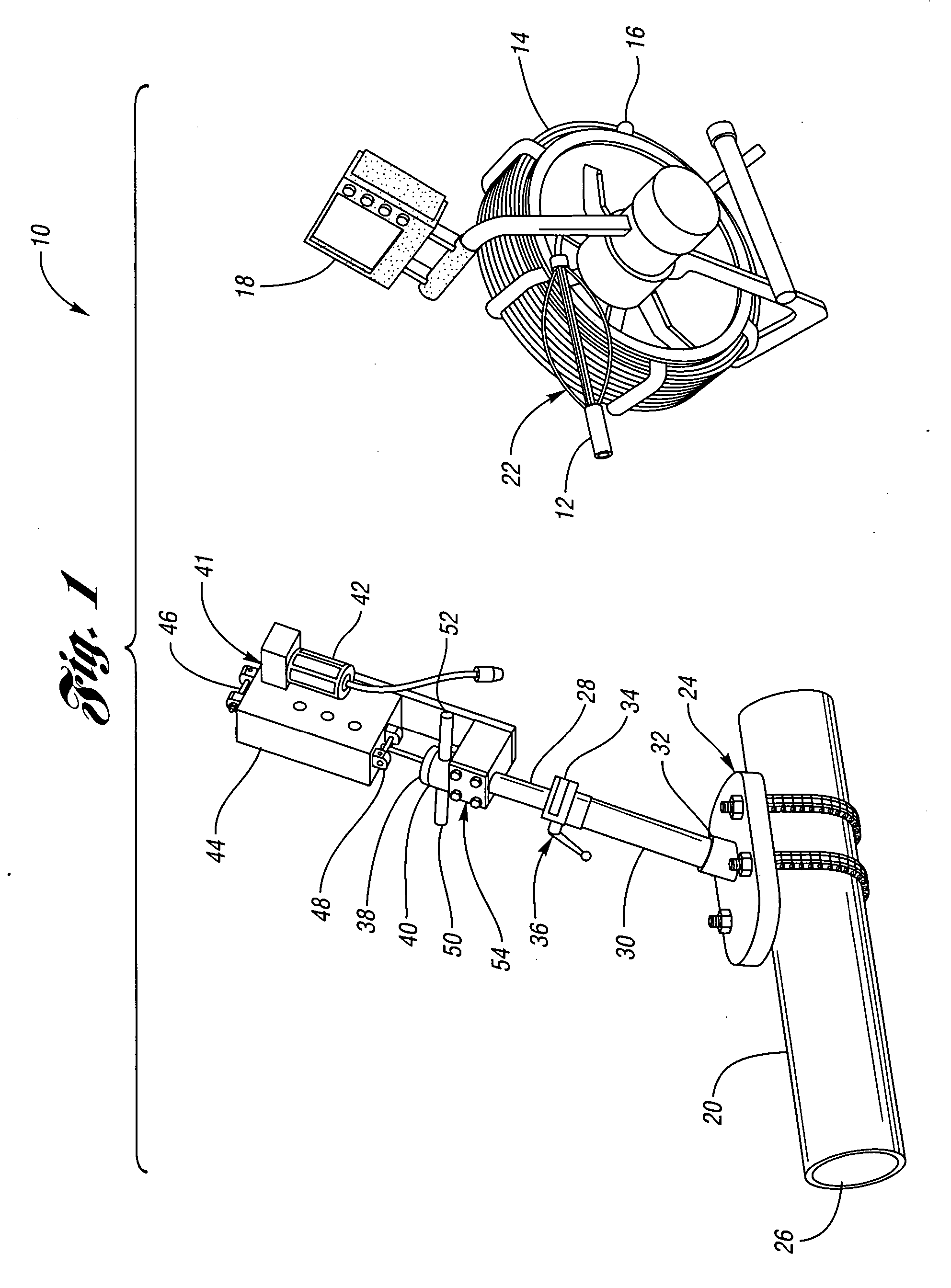
[0019]FIG. 1 shows a partially schematic perspective view of a pipeline inspection system 10 in accordance with one embodiment of the present invention. The inspection system 10 includes a camera 12 which is attached to an elongate flexible guide member, or push rod 14. The push rod 14 is wound around a spool 16, which has a video display monitor 18 conveniently attached thereto. The monitor 18 is electrically connected to the camera 12, for providing images from inside a pipeline 20. As explained in detail below, a positioning system 22 is disposed between the camera 12 and the push rod 14 for positioning the camera 12 within a pipeline, such as the pipeline 20.

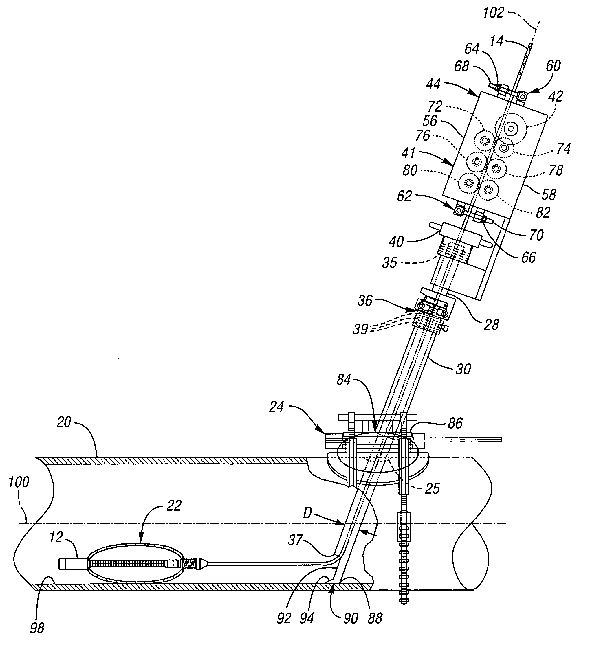
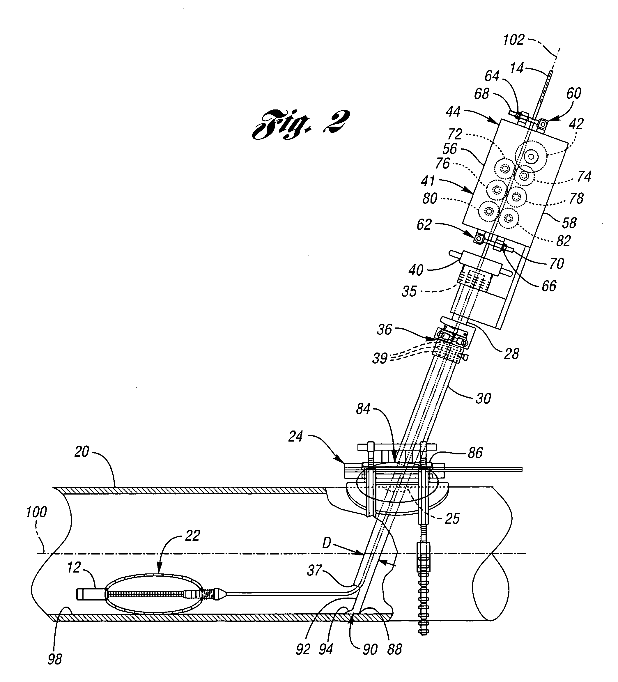
[0020] The pipeline 20 may be a high-pressure gas pipeline, for example, containing gas at 60 pounds per square inch (psi). To facilitate entry into the pipeline 20, a valve system 24 is used to provide selective access to an opening 25 in the pipeline 20. Any valve system that provides access to an interior 26 of the pipe...


PUM


Abstract

An inspection system configured for “no-blow” use in a pressurized gas pipeline includes a push rod wound around a spool for convenient deployment and portability. A camera disposed on one end of the push rod is configured to relay images back to a monitor. A motor is configured for remote actuation by an operator, and provides for self-propelled movement of the camera in the pipeline. An entry tube is configured for sealed entry into the pipeline to facilitate entry of the camera and push rod. A guide shoe at the end of the entry tube provides a smooth transition-for the camera and push rod as it leaves the entry tube and enters the pipeline. An automatically deployable and retractable positioning system is used to keep the camera away from an interior surface of the pipeline, and in the case of smaller pipelines, centers the camera within the pipeline.

Description

BACKGROUND OF THE INVENTION [0001] 1. Field of the Invention [0002] The present invention relates to a pipeline inspection system. [0003] 2. Background Art [0004] For more than 30 years, video inspection has been a baseline fundamental analytical tool for the evaluation and assessment of pipeline integrity. Originally developed as an aid for sewer system maintenance, video inspection equipment and techniques have played a key role in the development of “no-dig” and “trenchless” pipeline rehabilitation methods. This is because the choice of the best trenchless rehabilitation method, for any given application, is often largely based on the video inspection that takes place prior to the rehabilitation. Thus, the information gleaned from the pre-rehabilitation video inspection is used as the basis for key decisions that drive the entire rehabilitation process. [0005] The inspection of pipes often falls into two broad categories: inspections performed for purposes of preventative mainten...

Claims


Application Information

Patent Timeline
Patent Type & Authority Applications(United States)
IPC IPC(8): G01M19/00G01M99/00
CPCF16K7/10F16L41/06F16L2101/30F16L55/46G01N21/88F16L55/30F16L55/26G01N21/954
Inventor PENZA, G. GREGORYLOHR, GEORGEHERRLICH, HERMANN
Owner ULC TECH LLC
Why Eureka
Try Eureka