Pressure Differential System for Controlling High Pressure Refill Gas Flow Into On Board Vehicle Fuel Tanks

a technology of high pressure and fuel tank, which is applied in the direction of liquid handling, container discharging methods, packaged goods types, etc., can solve the problems of prohibitive use of mass flow meters by consumers, and achieve the effects of high pressure, stable operation, and shortening refueling tim

Active Publication Date: 2007-03-08
HONDA MOTOR CO LTD
View PDF12 Cites 47 Cited by
  • Summary
  • Abstract
  • Description
  • Claims
  • Application Information

AI Technical Summary

Benefits of technology

[0010] In brief, it is an object of the invention to use two or more pressure sensors to control the storage tank valves during a high pressure vehicle tank refill. The system described herein is principally for consumer use and provides essentially the same performance as a mass flow meter measuring method in sensing pressure to t...

Problems solved by technology

A traditional method requires an expensive flow meter in a high pressure...

Method used


Image

  • Pressure Differential System for Controlling High Pressure Refill Gas Flow Into On Board Vehicle Fuel Tanks
  • Pressure Differential System for Controlling High Pressure Refill Gas Flow Into On Board Vehicle Fuel Tanks
  • Pressure Differential System for Controlling High Pressure Refill Gas Flow Into On Board Vehicle Fuel Tanks

Examples


example 1

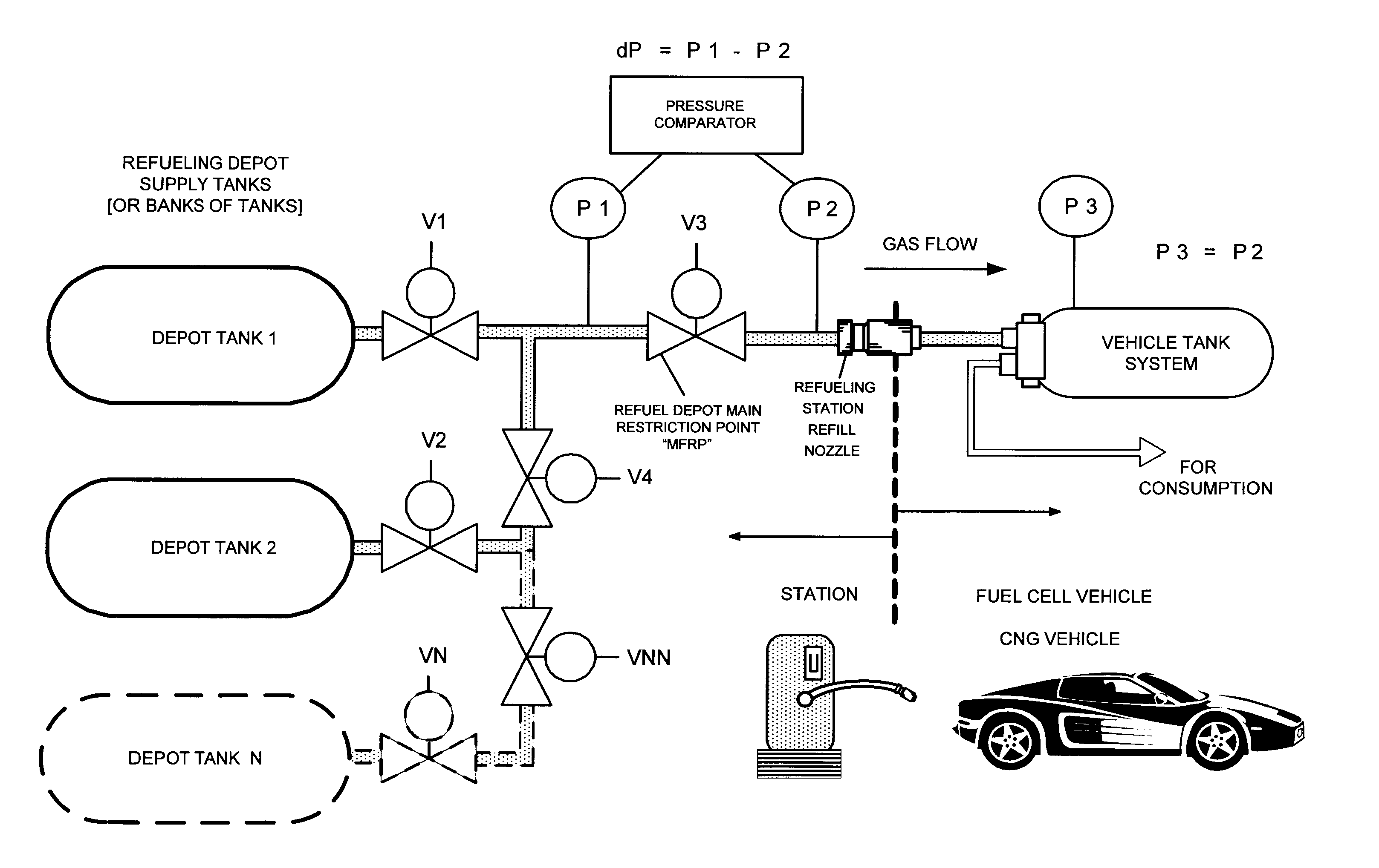
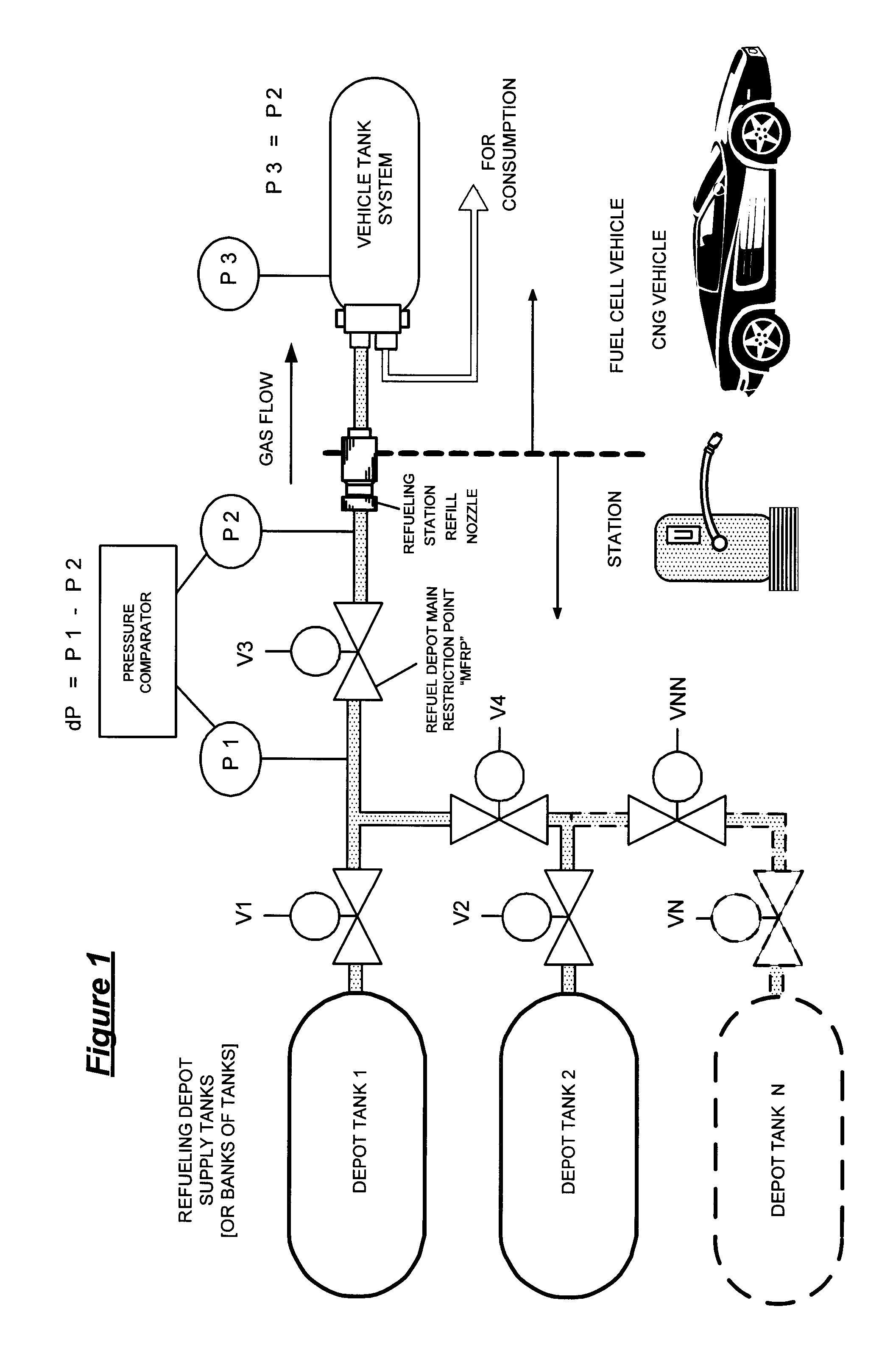
[0022] Example 1 in FIG. 1 illustrates an example of the dP method of the invention utilizing a bank of two tanks (A “bank” may have one or more tanks.) at a refilling station:

[0023] After connection of the refueling hose to the vehicle, refueling starts; valve V3 is opened; valve V1 is opened, then gas from tank 1 at the station flows to the vehicle tank. When dP=P1−P21 is finished and valve V1 is closed. If dP=0 (or approximately 0), and P1 and P2 equal a desired pressure for a full fill P3 (or otherwise), then the refill is complete. Valve V1 and valve V3 are closed. If further gas is required, valve V2 and valve V4 are opened; gas from tank 2 at the station flows to the vehicle tank. When dP=P1−P22 is finished and valve V2 and valve V4 are closed. If dP=0 (or approximately 0), and P1 and P2 equal a desired pressure for a full fill P3 (or otherwise), then the refill is complete. Valve V2, valve V4 and valve V3 are closed. The sequence above is repeated for other tanks N with val...

example 2

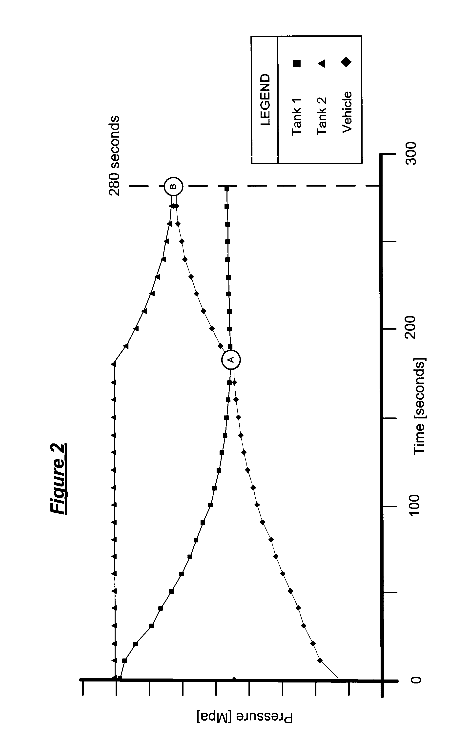
[0024]FIG. 2 is a chart illustrating a test of Example 1. Correct tank switching is provided and sufficient fuel pressure is achieved in the vehicle tank[s] in a reasonable time with little disturbance in refill fluid flow. Pressure in the refill depot bank of tanks, Tank 1 and Tank 2, and the vehicle tank (y-axis) is plotted against time on the x-axis. As tank 1 gas is consumed by the refill, pressure in tank 1 decreases as vehicle tank pressure increases in an almost inverse proportion. When pressure in tank 1 reaches a predetermined limit, at point “A,” the ECU switches to tank 2 whereby pressure in tank 2 equalizes with the vehicle tank pressure at point “B,” whereupon the refill is complete, namely Pvehicle=Ptank 2 or dP=0 at the MFRP. The ECU detects the pressure equalization and terminates the refill process.

example 3

[0025]FIG. 3 illustrates an example of an electronic control unit, ECU, for the dP method wherein sensors measure pressures and determine the differential between P1 and P2 at the main restriction point MFRP (station and vehicle sides of the depot dispenser). The ECU will control tank switching of gas flow from the tanks in the station bank through the vehicle refill gas flow circuit. The pressure difference at the refilling system main restriction point, namely the difference between pressures on opposite sides of the MFRP, station pressure side P1 and vehicle tank pressure side P2, should approach zero at a full consumption of gas from one tank in a bank or at a full fill. An optional main dispensing valve MDV at the front of the refill tanks controls overall on / off flow at the depot. The ECU may also monitor and control gas flow and switching, in parallel or series, or other predetermined sequence of the depot tanks and banks of tanks.


PUM

PropertyMeasurementUnit
Pressureaaaaaaaaaa
Flow rateaaaaaaaaaa

Abstract

A high pressure fuel flow control device wherein pressure sensors are interposed on either side of the main restriction point of a refueling depot when the vehicle tank(s) to be refilled are interconnected in a flow circuit that connects the refilling depot and the vehicle tanks. The sensors measure pressure on the side of the depot tank[s] and pressure on the side of the vehicle tank at a restriction point in the gas flow circuit. Flow from a tank is complete and a tank is switched when the difference in the pressures sensed on opposite sides of the restriction point approaches zero or slightly greater than zero.

Description

RELATED APPLICATIONS [0001] This application is related to and claims all benefits under 35 U.S.C. §119(e) of my earlier U.S. Provisional Patent Application Ser. No. 60 / 713,008 filed on Aug. 31, 2005, entitled “Pressure Differential System for Metering Gas Flow in Fuel Tanks for High Pressure Gas Fuel Powered Vehicles.”FIELD OF THE INVENTION [0002] The present invention relates to a system for efficiently refueling high pressure, on board, vehicle gas fuel tanks with hydrogen gas and / or compressed natural gas at a refueling station where high capacity, high pressure fuel storage tanks provide the fuel to the vehicle through a consumer dispensing means. BACKGROUND OF THE INVENTION [0003] Current systems used to refill vehicle storage tanks with high pressure hydrogen or compressed natural gas require an expensive flow meter in a high pressure environment. Because of the expense and complexity of high pressure gas metering, the use of flow meters at retail fuel depots is not likely to...

Claims


Application Information

Patent Timeline
IPC IPC(8): B65B31/00
CPCF17C5/00Y02E60/321F17C2201/056F17C2201/058F17C2205/0326F17C2205/037F17C2221/012F17C2221/033F17C2223/0123F17C2223/036F17C2225/0123F17C2225/036F17C2227/043F17C2250/0434F17C2250/075F17C2260/022F17C2265/065F17C2270/0168F17C2270/0184F17C13/025Y02E60/32
Inventor HANDA, KIYOSHI
Owner HONDA MOTOR CO LTD
Why Eureka
Try Eureka