
Method for joining plastic work pieces

a technology of laser welding and workpieces, which is applied in the field of laser welding to join plastic workpieces, can solve the problems of long handling time, inability to use the method in connection with microstructures, and color pigments to be added to the two workpieces, so as to achieve the effect of rapid manufacturing of functional components

Inactive Publication Date: 2007-03-08
KERNFORSCHUNGSZENTRUM KARLSRUHE GMBH
View PDF12 Cites 24 Cited by
  • Summary
  • Abstract
  • Description
  • Claims
  • Application Information

AI Technical Summary

Benefits of technology

The patent describes a method for joining transparent plastic materials using laser radiation. The method involves applying absorption layers to the workpieces, pressing them together, and heating them with a laser to join them. The absorption layers are made of carbon or gold and are deposited using vacuum vapor deposition or spraying techniques. The laser beam is focused onto the absorption layer to heat it and join the workpieces. The method can be used with various plastic materials such as PMMA, PP, and PVDF. The laser power and wavelength can be adjusted for optimal results. The method allows for precise and strong welds with minimal damage or deformation of the structures. The use of a third laser with a wavelength between 9 μm and 11 μm allows for high-precision cutting of the polymers. The combination of cutting and welding techniques can also be used to produce a three-dimensional structure.

Problems solved by technology

The method however has the disadvantage that color pigments have to be added to the two workpieces at different rates such that the material of one work piece is transparent for the spectrum of the laser beam and the other workpiece material is absorbent for the spectrum of the laser beam used.
Its disadvantage resides in a long handling time which is mainly caused by the common method used for the application of the absorber layer.
These methods are therefore not usable in connection with microstructures since the microstructures are detrimentally affected particularly by becoming deformed or forming fractures.

Method used


Image

  • Method for joining plastic work pieces
  • Method for joining plastic work pieces
  • Method for joining plastic work pieces

Examples


Embodiment Construction

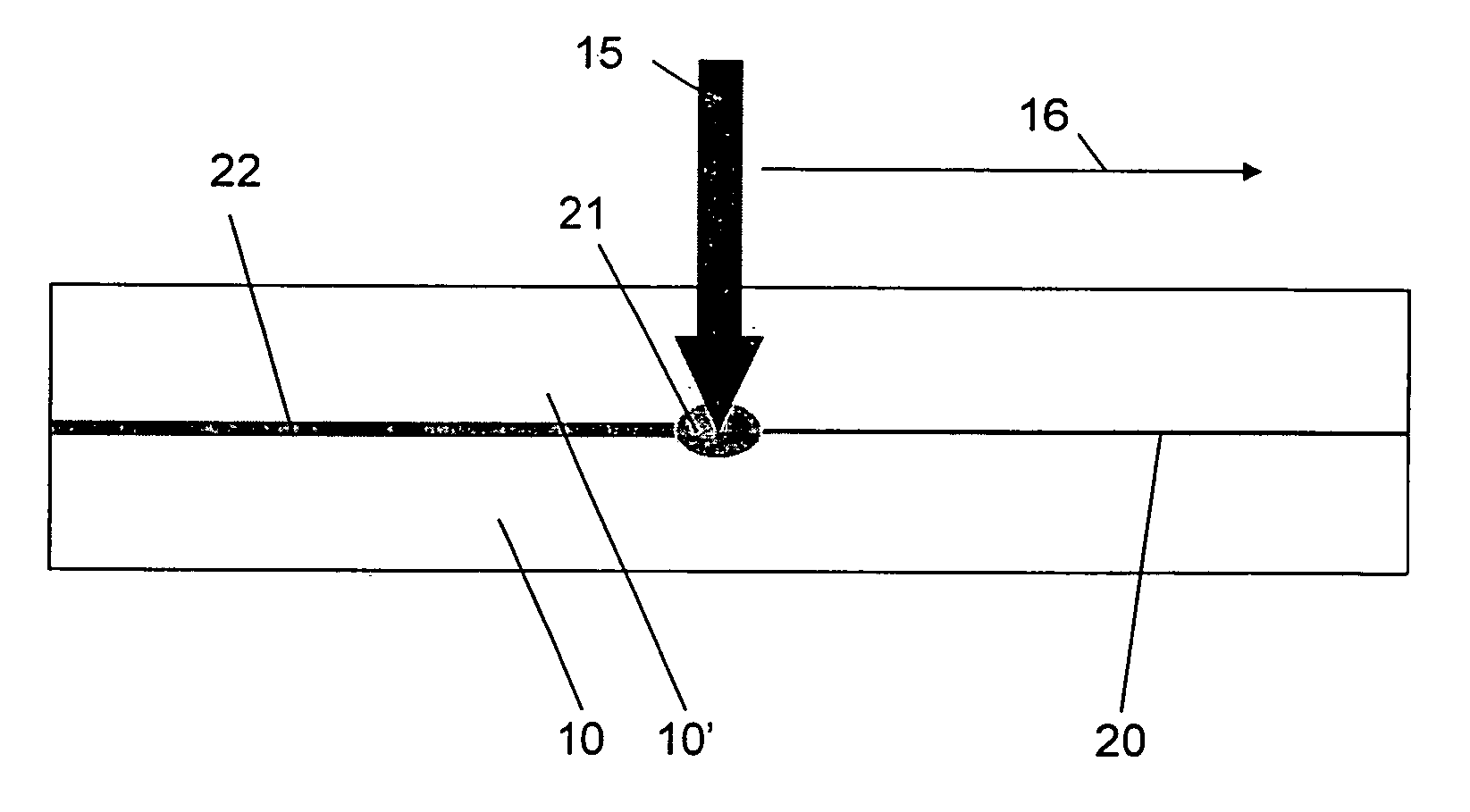
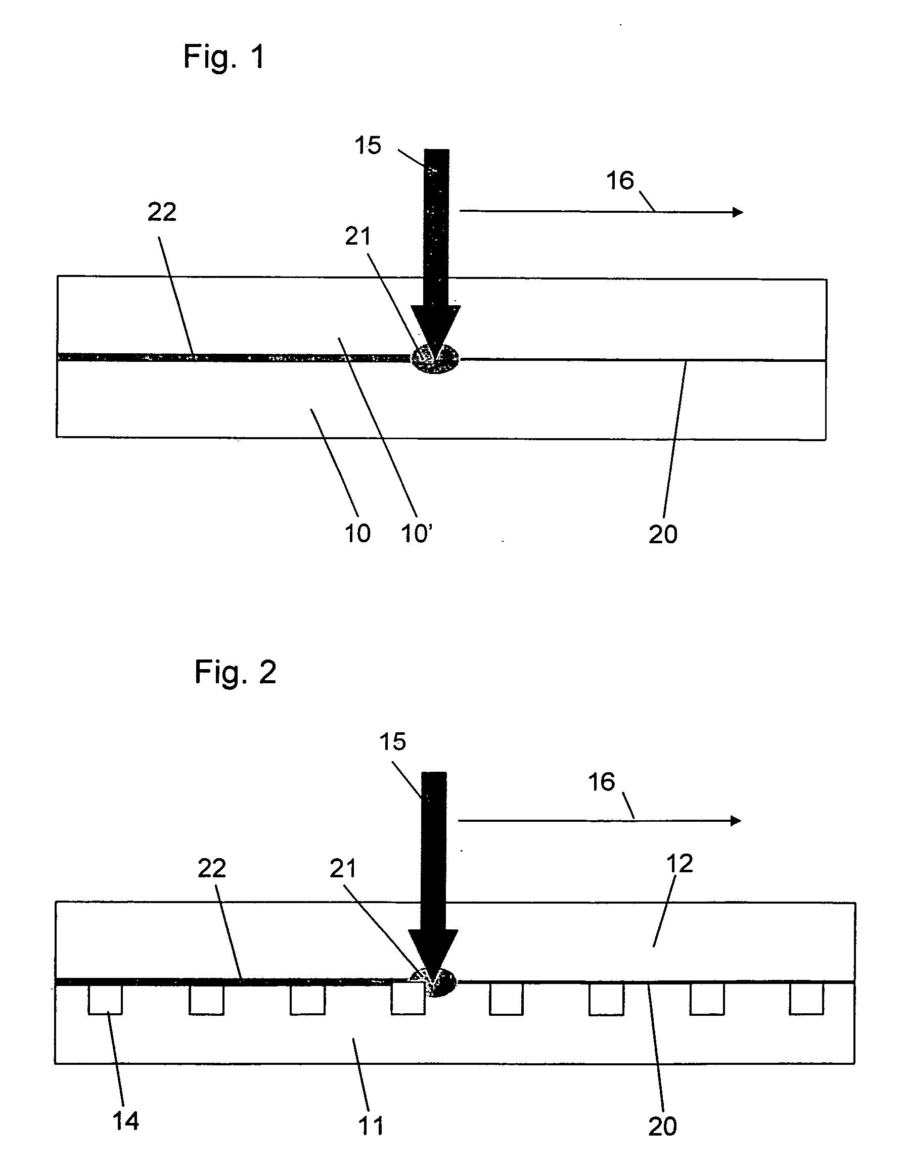
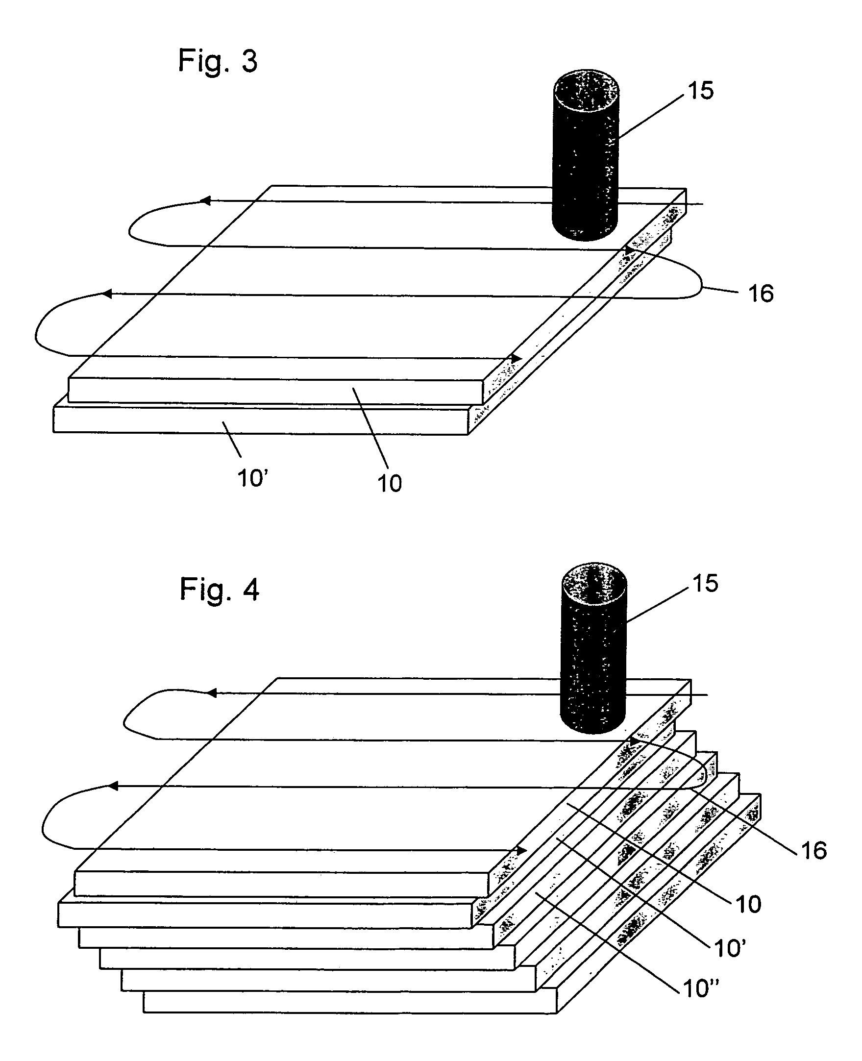
[0046]FIG. 1 shows schematically the method according to the invention for the joining of the two workpieces 10, 10″ of plastic material wherein an absorption layer 20 of carbon is applied to the workpiece 10. A laser beam 15 with a wavelength of 940 nm, which is focused onto the absorption layer 20 is moved along a path 16 (scanned). The scanning speed in the case of PMMA was 20-50 mm / s;

[0047] The scanning staggering was 200 μm.

[0048] The power of the laser beam 15 was so selected that the temperature in the laser-influenced zone 21 exceeds the glass temperature of the plastic (PMMA; 105° C., PC; 160° C.), whereby the absorption layer 20 is heated and, as a result, the two workpieces 10, 10′ are interconnected via the joining zone 22. During the laser scan the two workpieces were pressed together with a pressure of between 0.3 and 0.7 MPa (3 bar and 7 bar).

[0049]FIG. 2 shows a transparent microstructured polymer foil or plate 11 being joined by the method according to the invent...


PUM

PropertyMeasurementUnit
thicknessaaaaaaaaaa
thicknessaaaaaaaaaa
wavelengthaaaaaaaaaa

Abstract

In a method for joining work pieces of transparent plastic material, wherein absorption layers are applied to an interface area between the work pieces to be joined and, wherein the work piece areas to be joined are firmly engaged and pressed together, and the interface area is subjected to laser radiation so that the absorption layer is heated and the work pieces are joined by welding, the absorption layer consists of carbon or gold with a thickness of 5 nm to 15 nm.

Description

[0001] This is a Continuation-In-Part Application of International application PCT / EP2005 / 004536 filed Apr. 28, 2005 and claiming the priority of German application 10 2004 0303619.2 filed Jun. 24, 2004. BACKGROUND OF THE INVENTION [0002] The invention resides in a method for joining plastic work pieces by laser welding wherein the assembled work pieces are transparent in the visible spectral range and are provided with an absorption layer. [0003] Upon joining polymer workpieces by laser-based welding in accordance with the so-called radiographic welding method, an opaque polymer material is joined to a transparent polymer of the same type. In practice, for such tasks, radiation sources in the form of diode lasers have become the standard over Nd: YAG-lasers. [0004] DE 195 10 493 A1 discloses a method for the welding of workpieces of plastic material wherein two workpieces are joined along a joint area where laser radiation passes through the first workpiece and into the second work...

Claims


Application Information

Patent Timeline
Patent Type & Authority Applications(United States)
IPC IPC(8): B32B37/00B32B37/06B29C65/00B29C65/16B29C65/82B81C3/00
CPCB29C65/1606Y10T156/1064B29C65/1635B29C65/1661B29C65/1674B29C65/1683B29C65/8215B29C66/1122B29C66/43B29C66/73366B29C66/90B29C66/91216B29C66/91221B29C66/91943B29C66/929B29C66/939B29C66/9592B29K2023/06B29K2023/12B29K2027/16B29K2027/18B29K2033/12B29K2059/00B29K2069/00B29K2071/00B29K2075/00B29K2077/00B29K2079/08B29K2081/06B29K2305/14B29K2307/00B29K2995/0026B29L2011/0016B29L2031/14B29L2031/7496B29L2031/7504B29L2031/756B29L2031/778B29C65/1638B29C66/45B29C65/1654B29C66/91411B29C66/91431B29C66/91641B29C66/934B29C66/53461B29C66/836B29C65/1616B29C66/71B29C66/73921
Inventor PFLEGING, WILHELMBALDUS, OLIVERBALDINI, ALESSANDRO
Owner KERNFORSCHUNGSZENTRUM KARLSRUHE GMBH
Learn More