

Substrate assembly apparatus and method
a technology of substrates and assembly apparatuses, applied in the direction of chemistry apparatus and processes, instruments, applications, etc., can solve the problems of time-consuming process becoming a bottleneck in increasing the productivity of manufacturing substrates, generating dust and dirt, damaging substrates, etc., and achieves a high degree of accuracy
- Summary
- Abstract
- Description
- Claims
- Application Information
AI Technical Summary
Benefits of technology
Problems solved by technology
Method used
Image

Examples
first embodiment
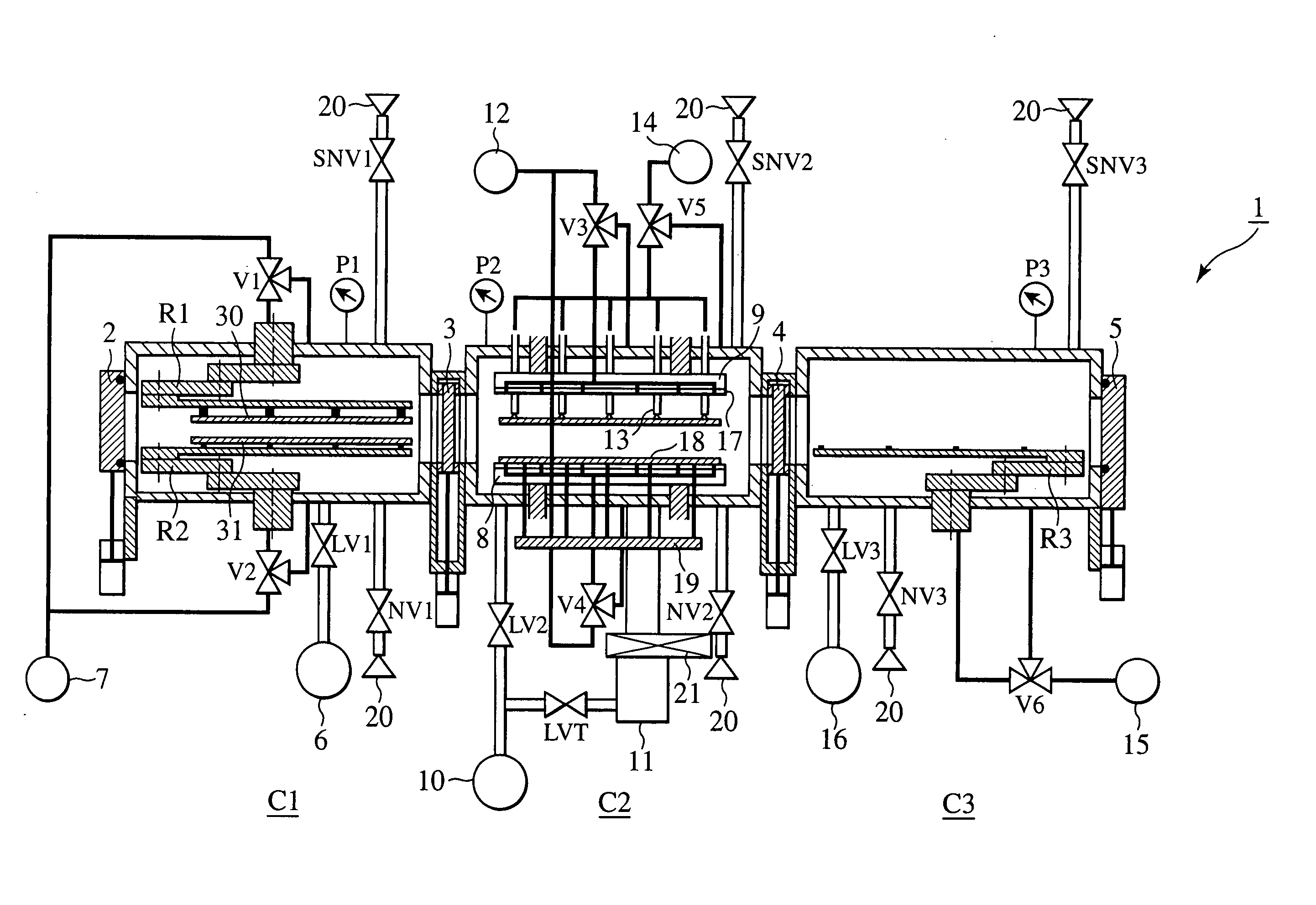
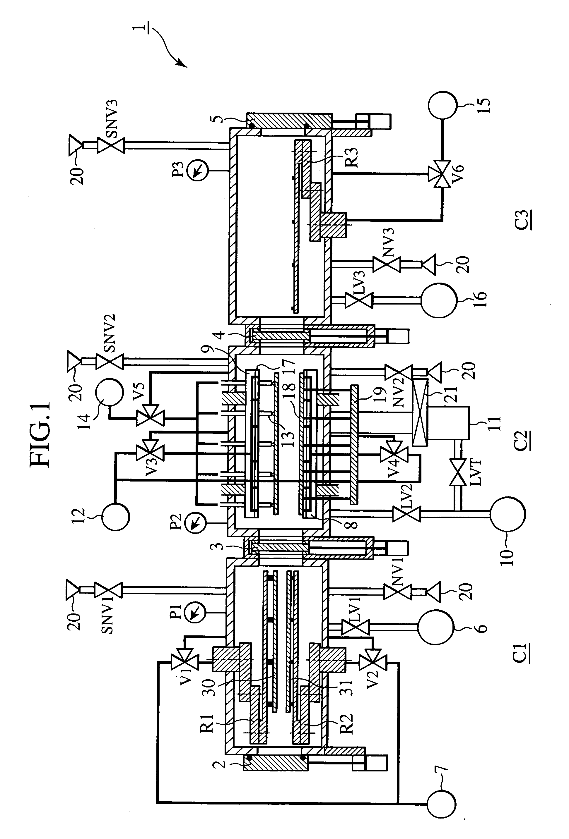
[0018] A substrate assembly apparatus or a substrate bonding apparatus according to the present invention will be described below with reference to FIGS. 1 to 4. Referring to FIG. 1, the substrate bonding apparatus 1 includes a first chamber C1, a second chamber C2, and a third chamber C3. The first chamber C1 is a pre-process chamber (substrate loading chamber), into which substrates are loaded. The second chamber C2 is a vacuum bonding chamber. The third chamber C3 is a post-process chamber, into which bonded substrates (liquid crystal panels) are unloaded. The first chamber C1 includes an upper substrate loading robot hand R1 and a lower substrate loading robot hand R2. These two robot hands R1, R2 are used for loading two substrates (an upper substrate 30 and a lower substrate 31). The third chamber C3 includes an unloading robot hand R3 for unloading bonded substrates. The substrate bonding apparatus 1 also has a first door valve 2, a first gate valve 3, a second gate valve 4, ...
second embodiment
[0057] the present invention incorporating a transport mechanism of a traveling dolly structure will be described with reference to FIGS. 5 and 6.
[0058] Like reference numerals refer to like elements between FIG. 5 and FIG. 1.
[0059] The second embodiment of the present invention depicted in FIG. 5 is widely different from the first embodiment of the present invention depicted in FIG. 1 in that a substrate loading dolly 51 is incorporated in the first chamber instead of the robot hands. The arrangement of the second embodiment of the present invention thereby eliminates the need for the suction pickup mechanism included in the robot hand. FIGS. 6A and 6B are views showing the loading dolly in detail.
[0060]FIG. 6A is a partial cross-sectional view of a first chamber and a second chamber. FIG. 6B is an enlarged view of the substrate loading dolly. The substrate loading dolly 51 is a two-tier structure transporting a lower substrate 31 on a lower tier and an upper substrate 30 on an u...
third embodiment
[0066]FIGS. 7A and 7B are views showing the present invention.
[0067] A substrate loading mechanism according to the third embodiment of the present invention will be described with reference to FIGS. 7A and 7B. A cylinder 71 for driving a pinion shaft is disposed externally below a first chamber C1. A pinion 70P having gear teeth formed on an upper and lower sides thereof is rotatably mounted on a leading end of the cylinder shaft. Two guide plates 72 extending in the transport direction are disposed on both sides of the first chamber C1 so that substrates can be transported. Each of the guide plates 72 includes a plurality of support pins 74 that contact and support the substrate. The guide plate 72 on a first side includes a straight rack 70R2 for transmitting a drive force. It is arranged so that the gear teeth formed on the upper side of the aforementioned pinion 70P engages with the rack 70R2. Further, a rack 70R1 in meshing engagement with the gear teeth on the lower side of t...
PUM
| Property | Measurement | Unit |
|---|---|---|
| Pressure | aaaaa | aaaaa |
| Pressure | aaaaa | aaaaa |
| Pressure | aaaaa | aaaaa |
Abstract
Description
Claims
Application Information