Resonator type filter

a filter and resonance technology, applied in the direction of impedence networks, electrical apparatus, piezoelectric/electrostrictive/magnetostrictive devices, etc., can solve the problems of deteriorating transmitting-band attenuation levels, difficult to ignore the resistance components of the material(s) forming the package, etc., to improve the deterioration of attenuation levels, improve the effect of connection resistance value and improve the effect of attenuation level

Inactive Publication Date: 2007-03-08
HITACHI MEDIA ELECTORONICS CO LTD
View PDF3 Cites 13 Cited by
  • Summary
  • Abstract
  • Description
  • Claims
  • Application Information

AI Technical Summary

Benefits of technology

[0038] As described above, the resonator type filter of the present invention can improve attenuation levels in a lower-frequency attenuation band by utilizing a function of the serial arm resonator not affected by the connection means leading to an external circuit. Thus, necessary attenuation characteristics can be achieved in a compact package, even when the filter adopts a next-generation form of

Problems solved by technology

As the package for housing the filter chip is miniaturized, wire bonding, using the VIA holes in the package, and using other means of connection to external circuits will necessarily make it difficult to ignore the resistance components of the material(s) forming the package.
For the resonator type filters, there has been th

Method used


Image

  • Resonator type filter
  • Resonator type filter
  • Resonator type filter

Examples


first embodiment

[0056] A first embodiment of the present invention is described below with reference to FIGS. 1 to 6.

[0057] The present invention connects an additional resonator in parallel to at least one serial arm resonator in order to improve deterioration of filter characteristics due to an increase in a resistance value of a connection element with an increase in packaging density. The fact that an attenuation level at a lower-frequency side can be improved by adding a parallel resonator to the serial arm resonator is described in detail using the graphs that represent more specific frequency characteristics.

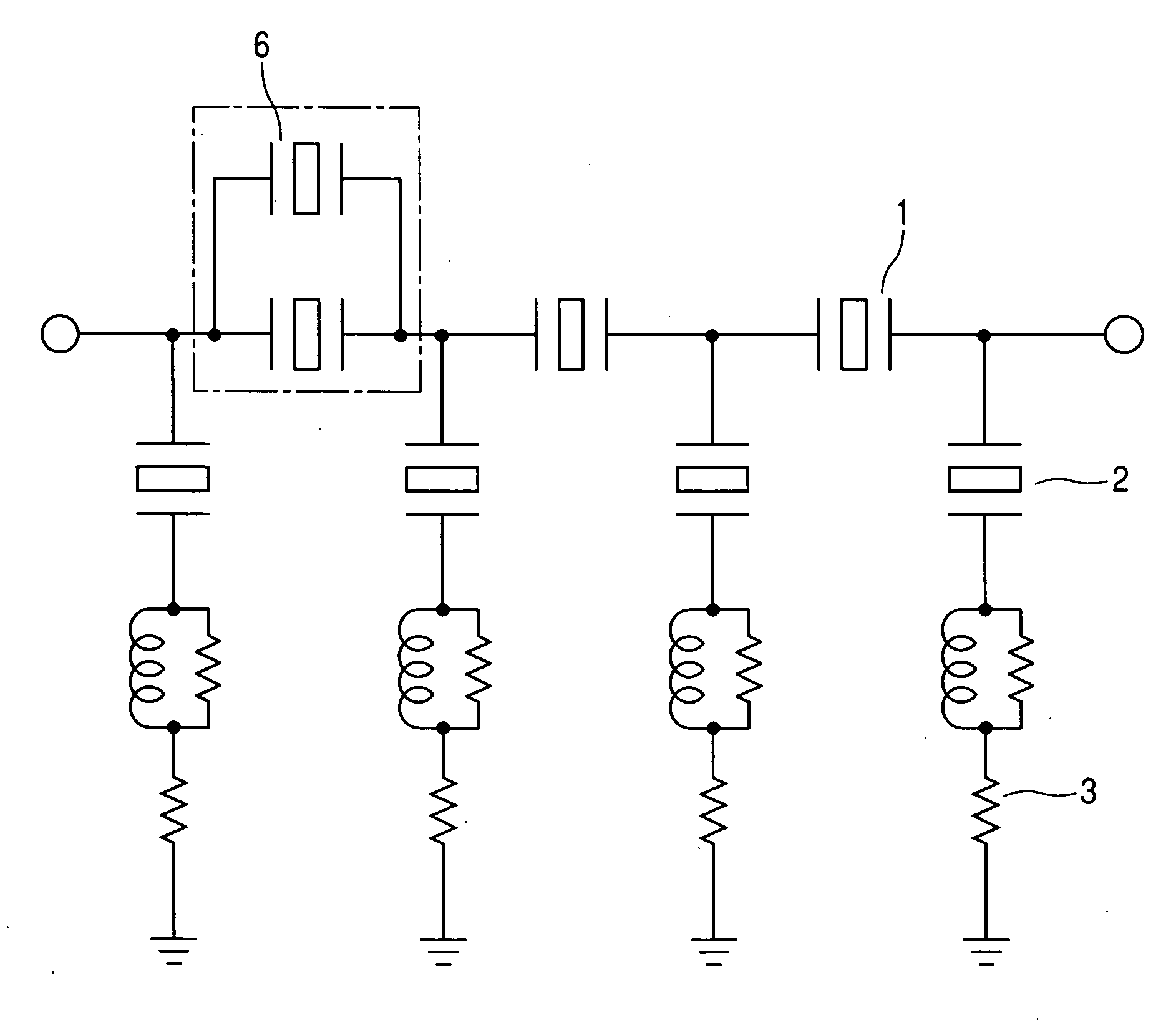
[0058]FIG. 1 is a diagram showing an equivalent circuit of a resonator type filter according to the present invention.

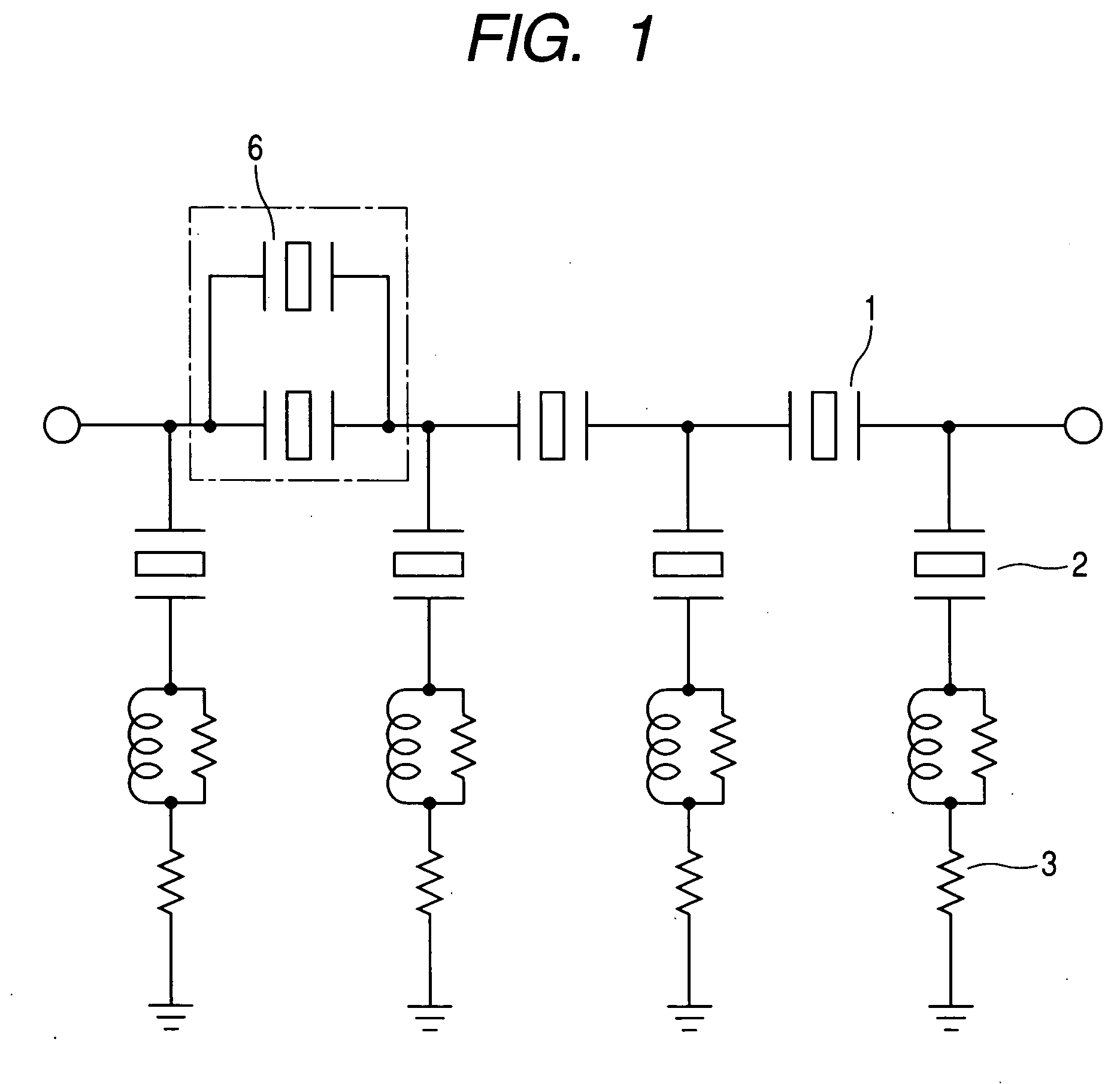
[0059]FIG. 2 is a graph that represents frequency characteristics of an imaginary part of impedance in a serial arm resonator which forms the resonator type filter according to the present invention.

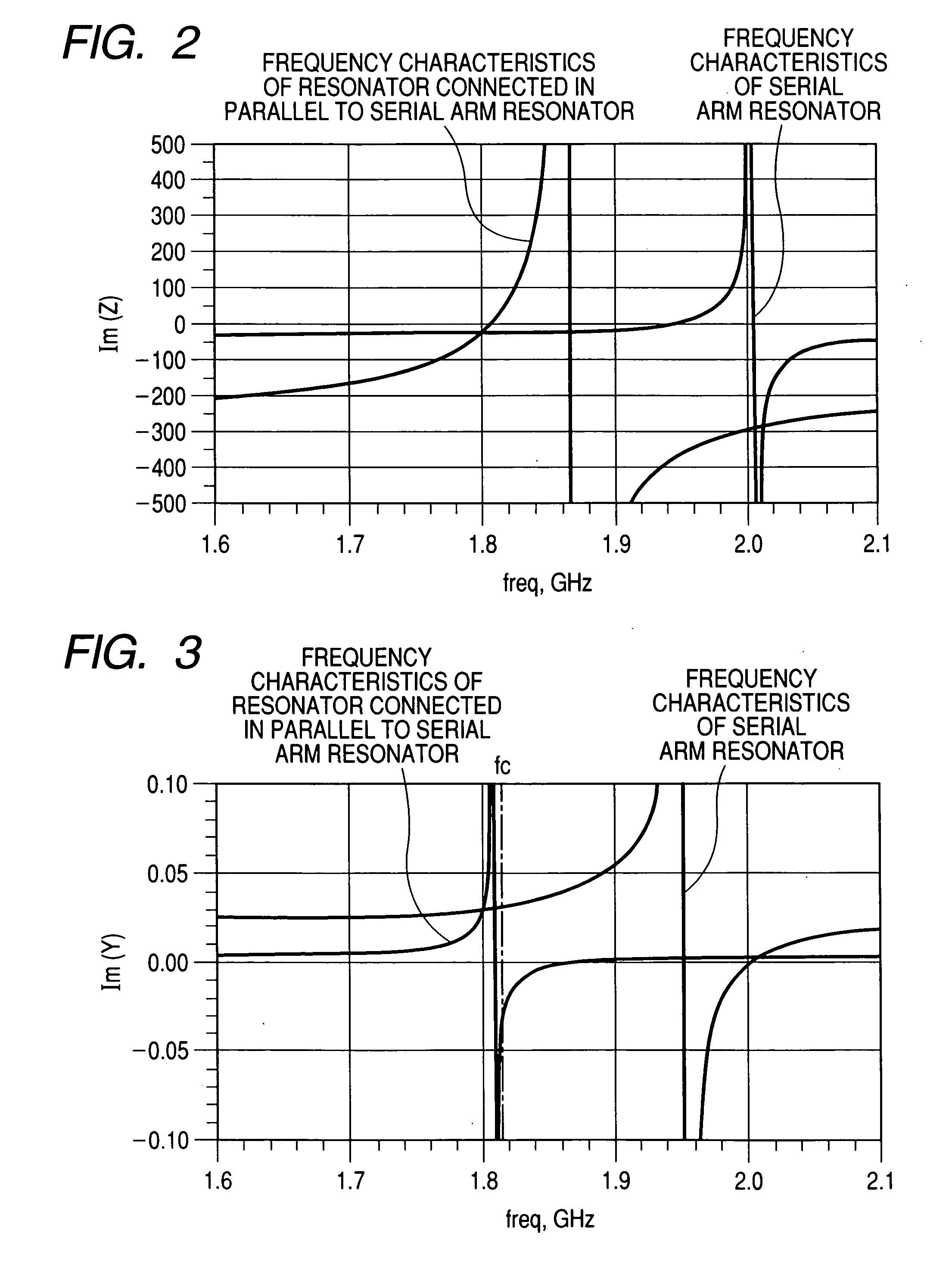
[0060]FIG. 3 is a graph that represents frequency characteristics of ...

second embodiment

[0073] A second embodiment of the present invention is described below with reference to FIG. 8.

[0074]FIG. 8 is a diagram showing an example of patterns in a surface acoustic wave resonator.

[0075] The present embodiment applies to a specific example of connecting two resonators in parallel in a surface acoustic wave resonator. In this surface acoustic wave resonator, a serial arm resonator can be connected in parallel to a resonator formed up of an interdigital transducer (IDT) 7 and a reflector 8, by disposing, as in FIG. 8A, a reflector formed up of an IDT 9 and a reflector 10. Also, the reflectors disposed between the IDTs 7 and 9 are integrally formed as in FIG. 8B to provide a reflector 11, thereby making it possible to minimize an increase in chip area due to the resonator connected in parallel to the serial arm resonator.

third embodiment

[0076] A third embodiment of the present invention is described below with reference to FIG. 9.

[0077]FIG. 9 is a diagram showing an equivalent circuit with an inductance element further added in series to a resonator 6 of a serial arm added in parallel.

[0078] The present embodiment applies to a specific example of applying a configuration of the present invention to a BAW (Bulk Acoustic Wave Resonator) resonator such as an FBAR (Filmed Bulk Acoustic Wave Resonator) or SMR (Solidly Mounted Resonator).

[0079] Although resonance frequencies of a surface acoustic wave resonator can be arbitrarily set at basic periods of IDTs, resonance frequencies of a BAW resonator needs to be controlled by adjusting a thickness of a piezoelectric thin film, so if too much flexibility of resonance frequency setting is sought, this will increase the number of man-hours in a manufacturing process, thus resulting in increased costs. The present embodiment proposes a method of solving this problem. It ha...


PUM


Abstract

A resonator is connected in parallel to at least one serial-arm-connected resonator in a resonator type filter having a serial arm and a parallel arm. At this time, the resonance frequency of the resonator connected in parallel is set to be substantially the same as the resonance frequency of the parallel-arm-connected resonator. This makes it possible to prevent the deterioration of attenuation levels at the lower-frequency side of the filter, caused by an increase in the resistance of a connection element due to an increase in packaging density.

Description

CLAIM OF PRIORITY [0001] The present application claims priority from Japanese application JP 2005-260092 filed on Sep. 8, 2005, the content of which is hereby incorporated by reference into this application. FIELD OF THE INVENTION [0002] The present invention relates to resonator type filters, and more particularly, to a resonator type filter suitable for use in a filtering device which separates the GHz-band high-frequency output signals or input signals used for communications devices such as hand-held telephones. BACKGROUND OF THE INVENTION [0003] In recent years, it is becoming absolutely necessary for hand-held phones to have not only mere call-placing / receiving functions, but also a high-speed data communications function. Accordingly, demands for reduction in the areas / volumes of their high-frequency sections that implement communications are coming to be more stringent. Among these high-frequency sections, a filtering section, in particular, that sorts out necessary signals...

Claims


Application Information

Patent Timeline
IPC IPC(8): H03H9/70H03H9/72H03H9/58H03H9/64
CPCH03H9/6483H03H9/605
Inventor SHIBAGAKI, NOBUHIKOHIKITA, MITSUTAKA
Owner HITACHI MEDIA ELECTORONICS CO LTD
Why Eureka
Try Eureka