Cooling device using direct deposition of diode heat pump

a technology of diode heat pump and cooling device, which is applied in the direction of machine operation mode, lighting and heating apparatus, and device details of semiconductor/solid-state device, etc., can solve the problem of low efficiency of thermoelectric cooler, and achieve high overall reliability, long life, and compact package height

Inactive Publication Date: 2007-03-08
BOREALIS TECH LTD
View PDF99 Cites 8 Cited by
  • Summary
  • Abstract
  • Description
  • Claims
  • Application Information

AI Technical Summary

Benefits of technology

[0028] An advantage of using a diode heat pump is that, due to its compactness, the thin-film diode heat pump may contribute to a compact package height that is ideal for use in small electronic devices. There is no toxicity in the present invention, it has a very long lifespan and very high overall reliability as diode devices are extremely robust compared to Peltier/thermoelectric devices which have high overall reliability only within their temperature regions. The operating temperature region

Problems solved by technology

This solves the problem of substantial thermal flow of heat due to the layers of insulating material resulting in the low level of efficiency of t

Method used


Image

  • Cooling device using direct deposition of diode heat pump
  • Cooling device using direct deposition of diode heat pump
  • Cooling device using direct deposition of diode heat pump

Examples


first embodiment

[0050]FIG. 10 shows the present invention in which the diode heat pump is constructed in situ on top of the die.

[0051] In step 300 a material suitable for being a first electrode 30 is deposited directly onto die 18. In step 310 the construction of diode heat pump 16 is completed. A second electrode 26 is positioned such that electrodes 30 and 26 are separated by a gap 28 through which electrons can tunnel. In step 320, heat sink 12 is attached to diode heat pump 16 so that heat produced by die 18 can be continually pumped away.

[0052] Direct deposition of electrode 30 onto die 18 may be done using techniques such as molecular beam epitaxy (MBE) and metal organic chemical vapor deposition (MOCVD). MBE and MOCVD are vapor deposition techniques used to deposit layers of materials on a substrate at the atomistic level. These techniques are chosen because of the precise control that they give over deposition of thin films. Other examples include approaches commonly used in the art. It i...

second embodiment

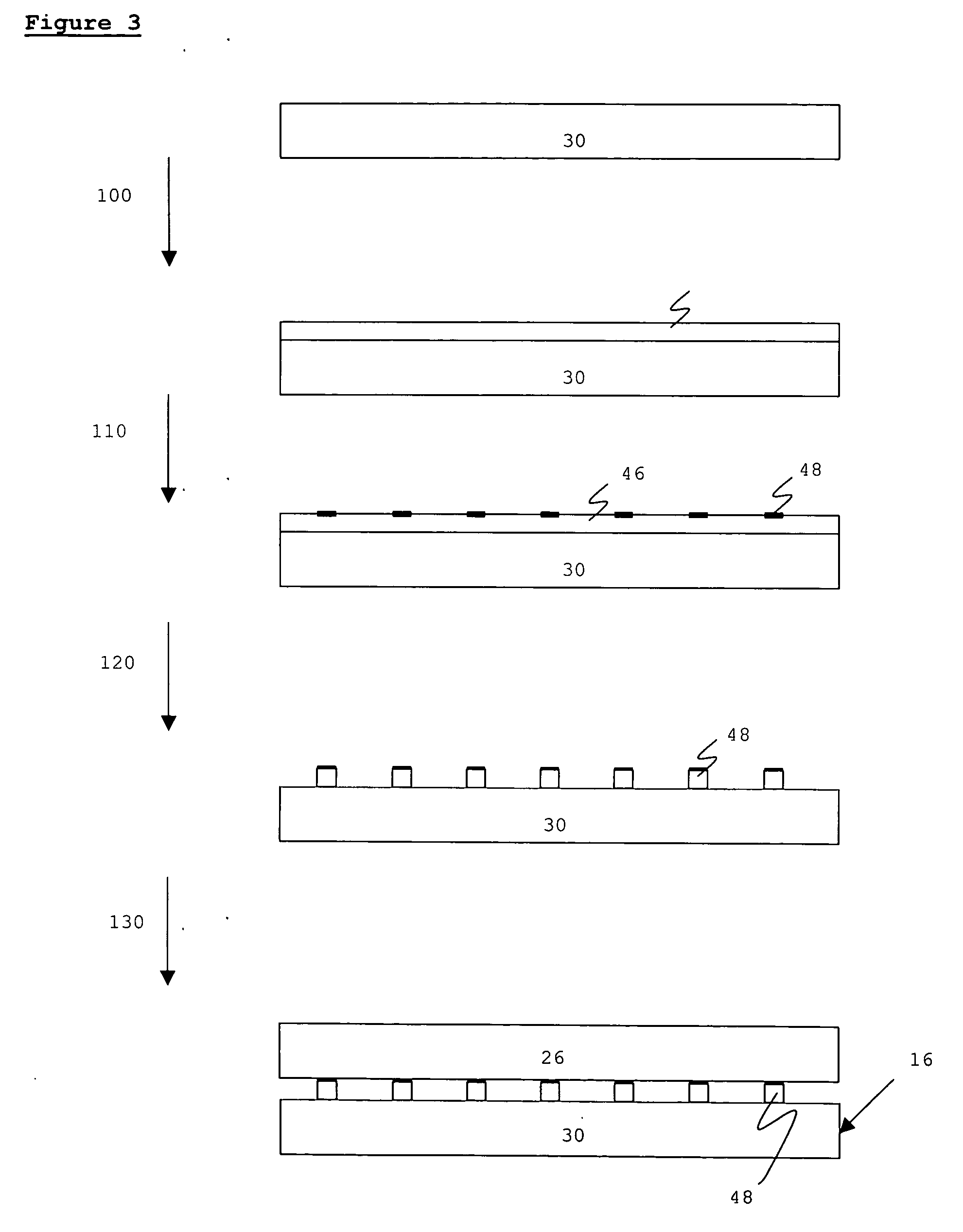
[0060]FIG. 11 shows the present invention, in which diode heat pump 16 is attached to die 18 after each unit has been manufactured independently. In step 400 diode heat pump 16 is constructed comprising two electrodes 30 and 26 separated by a gap 28 through which electrons can tunnel. In step 410 completed diode heat pump 16 is attached to die 18 using vapor deposition techniques as disclosed above. In step 420 heat sink 12 is attached to diode heat pump 16 so that heat produced by die 18 can be pumped away.

[0061] Diode heat pump 16 may be as disclosed in FIG. 1 or further embodiments known to those skilled in the art may be used. It is understood that the present invention is not limited to those embodiments.

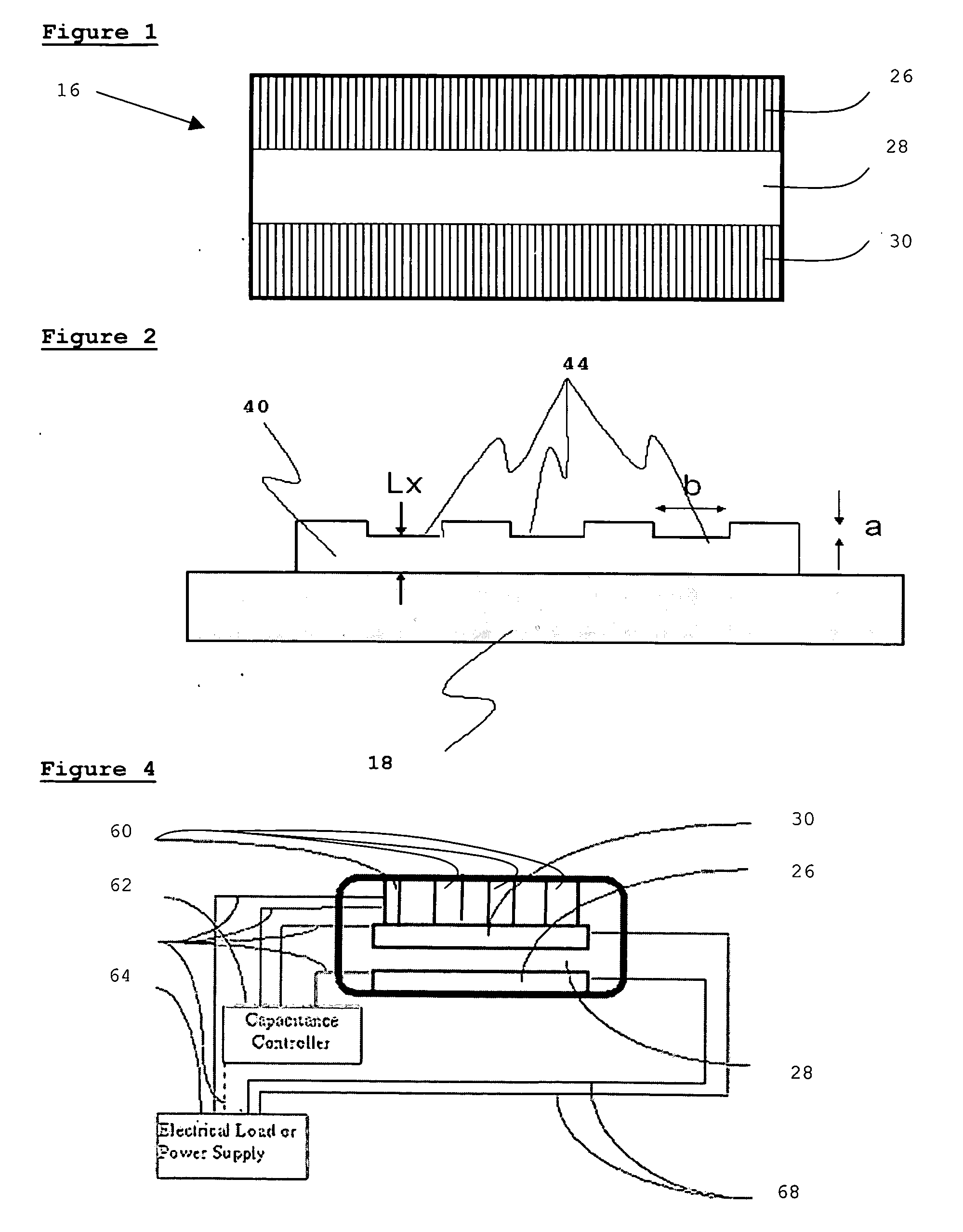
[0062] In one embodiment diode heat pump 16 may utilize modified electrode 40 disclosed in FIG. 2. Diode heat pump 16 is constructed utilizing modified electrode 40 as its first electrode and is then attached to die 18 as disclosed above.

[0063] Gap 28 may be maintained by spa...


PUM


Abstract

A diode heat pump is disclosed which may be deposited directly onto a processor unit using thin-film deposition techniques to achieve more efficient cooling. The diode heat pump is either formed in situ on the processor unit or attached to the processor unit after each unit has been manufactured. Further embodiments of diode heat pumps are also disclosed.

Description

CROSS-REFERENCE TO RELATED APPLICATIONS [0001] This application claims the benefit of U.K. Provisional Patent App. No. GB0518132.6, filed Sep. 6, 2005. BACKGROUND OF THE INVENTION [0002] This invention relates generally to cooling of electronic devices using diode heat pumps. Definitions: [0003]“Cool Chip” is hereby defined as a device that uses electrical power or energy to pump heat, thereby creating, maintaining, or degrading a thermal gradient. Cool Chips may accomplish this using thermionics, thermotunneling, or other methods as described in this application. It is understood that the present invention relates to Cool Chips. [0004]“Gap Diode” is defined as any diode which employs a gap between the anode and the cathode, or the collector and emitter, and which causes or allows electrons to be transported between the two electrodes, across or through the gap. The gap may or may not have a vacuum between the two electrodes, through Gap Diodes specifically exclude bulk liquids or ...

Claims


Application Information

Patent Timeline
IPC IPC(8): H01S3/04F25B21/00H01L23/34H01L23/38
CPCF25B21/00F25B2321/003H01L23/34H01L23/38H01L2224/16H01L2924/01055H01L2924/01079H01L2924/15311H01L2924/16195Y02B30/66H01L2924/01019H01L2224/73253Y02B30/00
Inventor COX, ISAIAH WATAS
Owner BOREALIS TECH LTD
Why Eureka
Try Eureka