Three flow architecture and method for aircraft OBIGGS

Active Publication Date: 2007-03-08
PARKER INTANGIBLES LLC
View PDF12 Cites 42 Cited by
  • Summary
  • Abstract
  • Description
  • Claims
  • Application Information

AI Technical Summary

Benefits of technology

[0011] The present invention provides an air separation system and method wherein the outlet of a primary air separation module (one or more modules or bundles of fiber membranes) is split into two flow paths, a low flow path and a high flow path. The outlet of a secondary air separation module (one or more modules or bundles of fiber membranes) is split into two flow paths, a mid flow path and a high flow path, the latter being joined with the

Problems solved by technology

However, since the fiber walls are more permeable to oxygen than nitrogen, the non-permeating gas stream becomes oxygen deficient and nitrogen enriched, while the permeating gas stream is oxygen enriched and nitrogen deficient.
This use of engine bleed air can decrease engine performance and can lead to increased fuel consumption.
Consequently, there is typically a large inrush of outside air into the ullage space during the descent regime.
The inerting of an airplane fuel tank t

Method used


Image

  • Three flow architecture and method for aircraft OBIGGS
  • Three flow architecture and method for aircraft OBIGGS
  • Three flow architecture and method for aircraft OBIGGS

Examples


Embodiment Construction

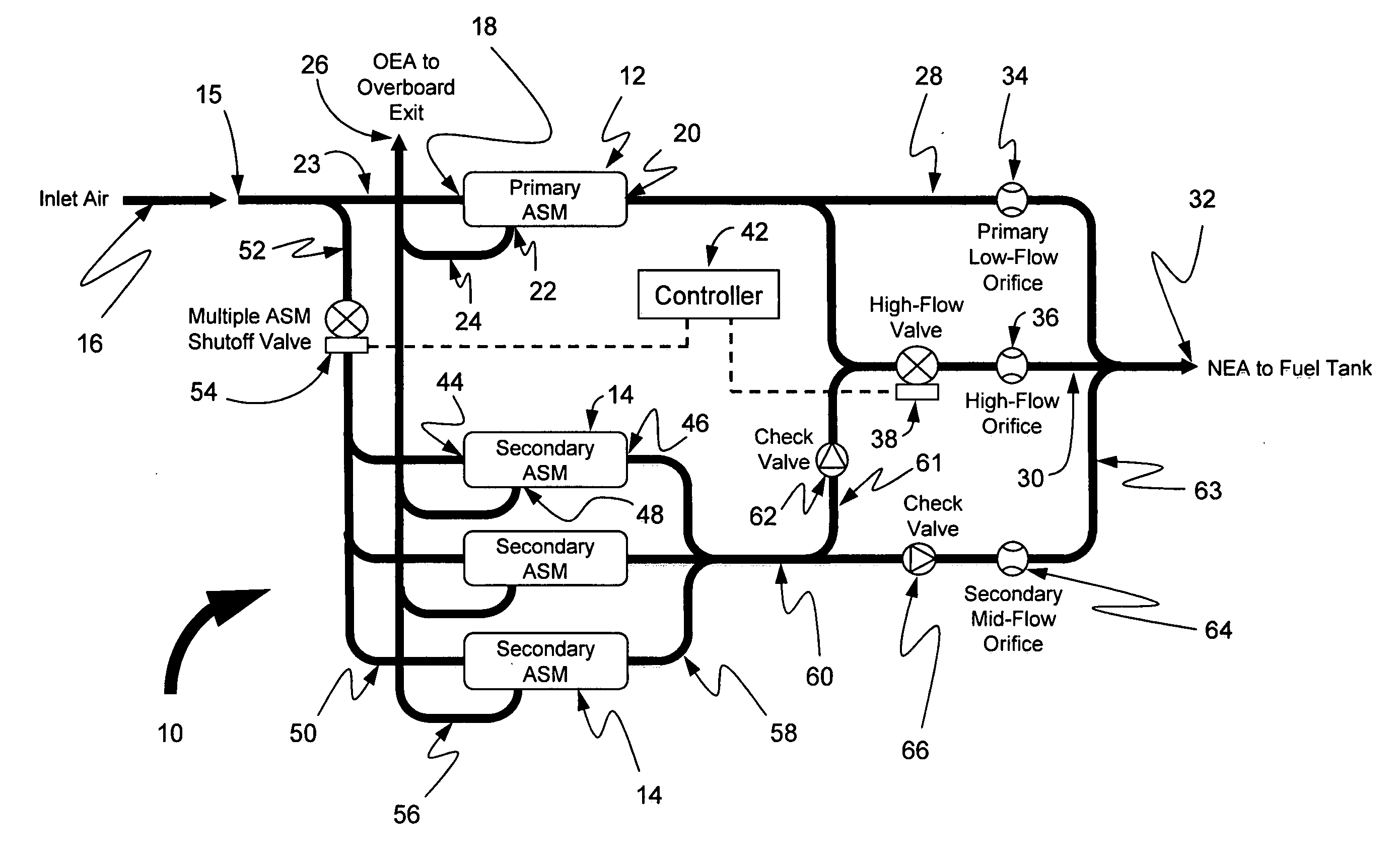
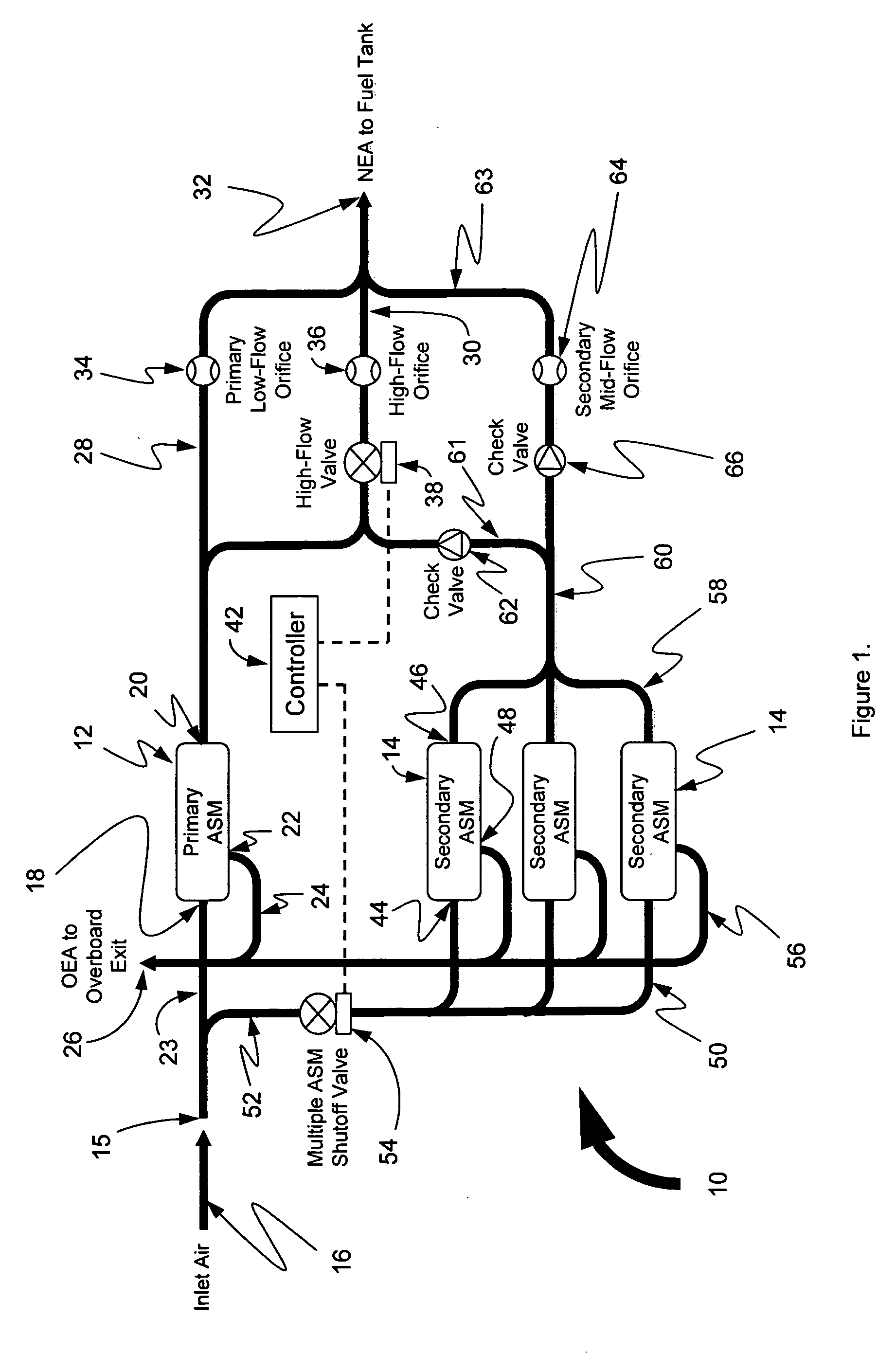
[0027] Referring now in detail to the drawings and initially to FIG. 1, an exemplary embodiment of an air separation system according to the invention is indicated generally by reference numeral 10. The illustrated system 10 is designed for use in an on-board inert gas generating system of an aircraft that supplies nitrogen-enriched air (NEA) to the fuel tank or tanks of an aircraft, and thus will chiefly be designed in this context. It will be appreciated, however, that the NEA can be used for inerting cargo holds and other void spaces in an aircraft. Moreover, the underlying principles of the invention have applicability to non-aircraft applications where a need exists for a supply of relatively inert, nitrogen-enriched air.

[0028] The system 10 generally comprises a primary air separation module 12 and one or more secondary air separation modules 14. Usually only one primary air separation module (ASM) will be utilized to produce nitrogen-enriched air (NEA) from a suitable supply...


PUM

PropertyMeasurementUnit
Timeaaaaaaaaaa
Temperatureaaaaaaaaaa
Flow rateaaaaaaaaaa

Abstract

An air separation system and method wherein the outlet of a primary air separation module (one or more modules or bundles of fiber membranes) is split into two flow paths, a low flow path and a high flow path. The outlet of a secondary air separation module (one or more modules or bundles of fiber membranes) is split into two flow paths, a mid flow path and a high flow path, the latter being joined with the high flow of the primary air separation module. Flow along the primary low flow passes through a low-flow orifice, flow along the secondary mid-flow path passes through a mid-flow orifice, and flow along the high flow paths of both the primary and secondary air separation modules is joined together for passage through a shutoff valve and a high flow orifice. This configuration allows for three different flow modes of operation.

Description

RELATED APPLICATION DATA [0001] This application claims the benefit of U.S. Provisional Application No. 60 / 646,145 filed Jan. 21, 2005, which is hereby incorporated herein by reference in its entirety.FIELD OF THE INVENTION [0002] The invention herein described relates generally to air separation systems and methods and particularly those that supply nitrogen enriched air to spaces to be inerted, such as the ullage space in an aircraft fuel tank. BACKGROUND OF THE INVENTION [0003] Aircraft have used on-board inert gas generating systems (OBIGGS) to protect against fuel tank explosions by replacing the potentially explosive fuel vapor / air mixture above the fuel in the ullage space of the tanks with nitrogen-enriched air (NEA). The NEA is generated by separating oxygen from local, ambient air and pumping the inert, oxygen impoverished NEA into the tanks. [0004] Production of NEA typically is carried out by means of an apparatus relying on permeable membranes, or else on molecular siev...

Claims


Application Information

Patent Timeline
IPC IPC(8): B64D13/02
CPCB64D37/32
Inventor JENSEN, BRYAN D.
Owner PARKER INTANGIBLES LLC
Why Eureka
Try Eureka