
Olfactory patch

a technology of olfactory patches and patches, which is applied in the field of olfactory patches, can solve the problems of difficult to provide deodorants and fragrances short-lasting effect of applying fragrance directly to the skin at a level to achieve the desired effect, and potential allergic reactions with such direct contact, etc., to achieve the effect of changing the physical structure of the olfactory, convenient re-filling or renewal, and flexible patch design

Inactive Publication Date: 2007-03-08
RASHID ASRAR
View PDF4 Cites 15 Cited by
  • Summary
  • Abstract
  • Description
  • Claims
  • Application Information

AI Technical Summary

Benefits of technology

[0004] The present invention relates to olfactory patches used to disseminate olfactory. Specifically, the olfactory may have various uses such as to provide fragrance, odours, or to have deodorising capability or be of therapeutic value.

Problems solved by technology

Applying an amount of fragrance directly to the skin at a level to produce a desired effect is only short-lasting.
In such circumstances it is difficult to provide deodorants and fragrances which are applicable to every individual and that have an extended period of action.
Thus, there is the potential for allergic reactions with such direct contact.
It will also be understood that the potential for controlled release of olfactory agents to mask bodily odours is difficult.
Aerosol type anti perspirants and deodorants may not be environmentally friendly due to their propellant gas.
However this device is dependant on the amount of olfactory that is deposited onto the fragrance-emitting layer.
Clearly the period of action is limited by the amount of fragrance within this fragrance-emitting layer.
Further, once the active agent is depleted from the active membrane, the same membrane cannot be refilled.
More recently sophisticated but expensive electronic release devices in the form of olfactory patches have been known.
As indicated these devices are expensive and tend to be relatively thick.

Method used


Image

  • Olfactory patch
  • Olfactory patch
  • Olfactory patch

Examples


Embodiment Construction

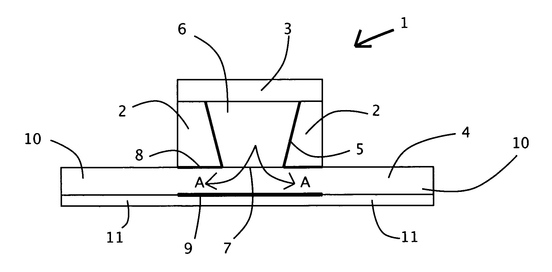
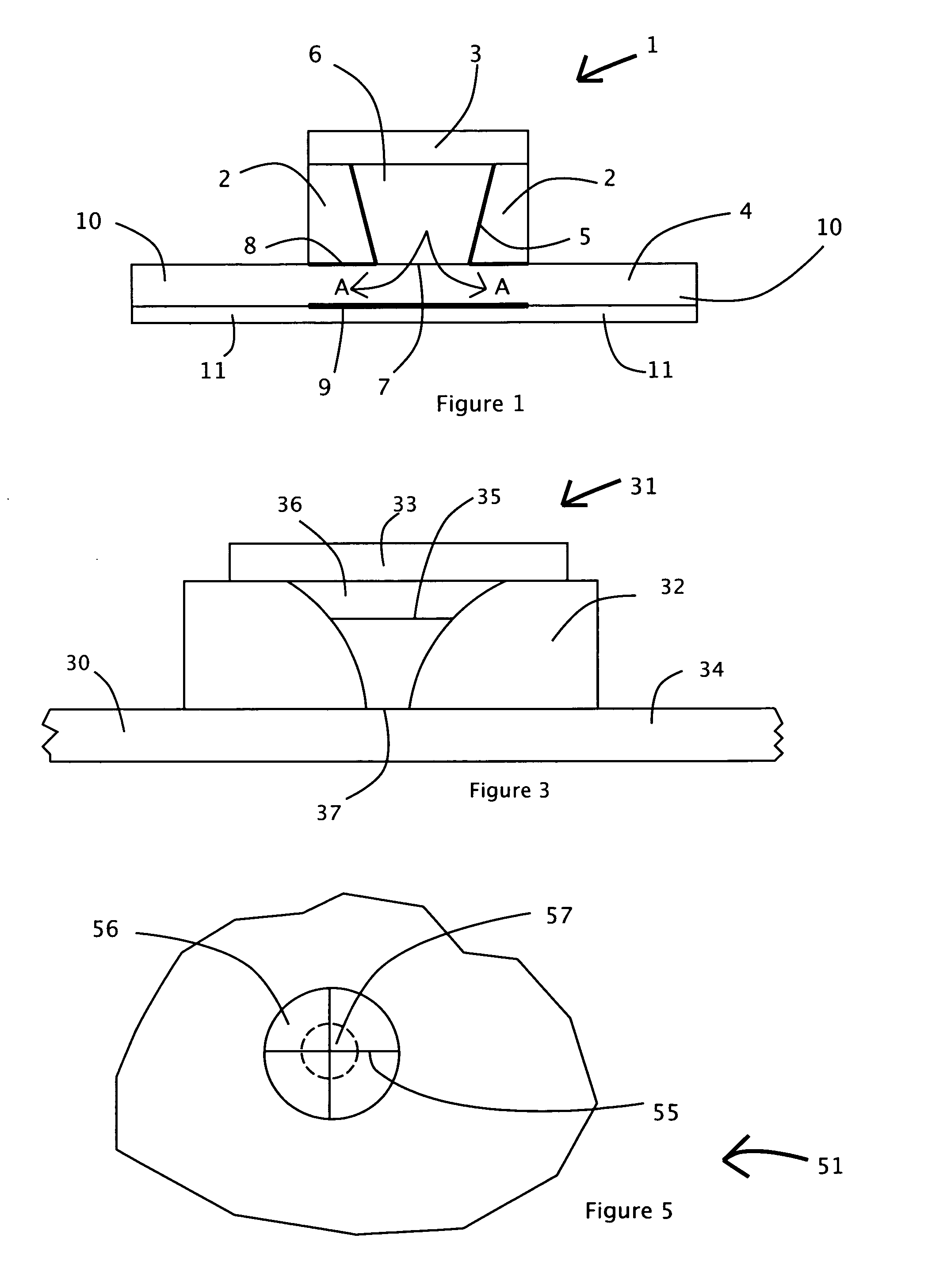
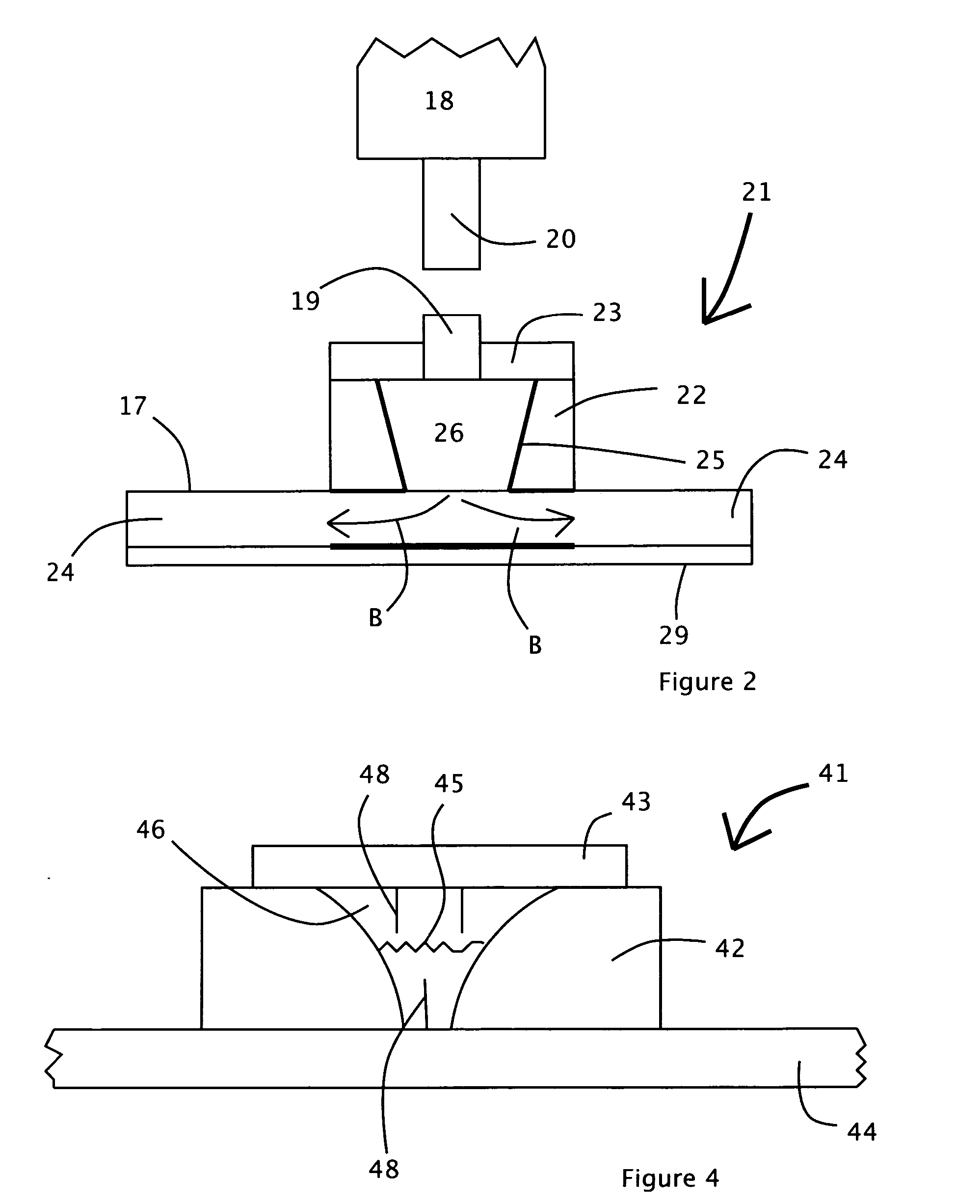
[0028] In accordance with the present invention there is provided an olfactory patch comprises a well formed by a reservoir layer, the well sandwiched between a barrier layer on a top side and a permeable layer on the bottom side, the permeable layer defining a pathway for an olfactory fluid flow from an olfactory fluid held in use in the well.

[0029] Preferably, the pathway is radial. Alternatively, the pathway is vertical or lateral from one side of the patch to the other.

[0030] Generally, the pathway has a preferential bias for radial flow or movement along the pathway. Typically the olfactory fluid flow is by diffusion from a high concentration to a lower concentration of fluid in the periphery of the permeable layer. The olfactory fluid is radiated or convectively released.

[0031] Typically, the pathway is defined between the reservoir layer and a surface upon which the permeable layer is secured in use. Typically the permeable layer is secured by adhesion. Normally, an adhesi...


PUM

PropertyMeasurementUnit
Digital informationaaaaaaaaaa
Timeaaaaaaaaaa
Pressureaaaaaaaaaa

Abstract

An olfactory patch comprises a well 6 formed by a reservoir layer 2, the well sandwiched between a barrier layer 3 and a permeable layer 4. The permeable layer defines a pathway for olfactory fluid flow from the well 6 (B, FIG. 2). The flow of the olfactory may be commenced by an initiator mechanism, the same or another mechanism may control or terminate the flow of olfactory. The olfactory patch may utilise any olfactory fluid or combination of fluids within the same patch. The patch may utilise olfactory fluid which provides aromas or masks odours or has de-deodorising capability or the olfactory fluid contains therapeutic agents which are released from the patch by aromatization or by direct skin absorption or by inhalation.

Description

CROSS-REFERENCE TO RELATED APPLICATIONS [0001] GB 0518253.0 FEDERALLY SPONSORED RESEARCH [0002] Not applicable SEQUENCE LISTING OR PROGRAM [0003] Not applicable BACKGROUND OF THE INVENTION—FIELD OF INVENTION [0004] The present invention relates to olfactory patches used to disseminate olfactory. Specifically, the olfactory may have various uses such as to provide fragrance, odours, or to have deodorising capability or be of therapeutic value. BACKGROUND OF THE INVENTION [0005] It will be understood that it is inherent with human beings perspiring that they will create bodily odours, which are not pleasant. Traditionally these odours have been masked with deodorants and fragrant body sprays such as perfumes as well as by provision of anti perspirant agents to reduce the perspiration causing the body odours. Applying an amount of fragrance directly to the skin at a level to produce a desired effect is only short-lasting. Nevertheless, it will be appreciated that perspiration builds ov...

Claims


Application Information

Patent Timeline
IPC IPC(8): B32B27/04A61M27/00A01M29/00A01M29/12A01M29/34
CPCA61K8/0208A61Q17/02A61Q15/00A61Q13/00Y10T442/2541Y10T442/2525A61K8/02
Inventor RASHID, ASRAR
Owner RASHID ASRAR
Learn More