
EMI rejection for temperature sensing diodes

a technology of temperature sensing diodes and emi, applied in heat measurement, process and machine control, instruments, etc., can solve the problems of increasing the power consumption of measuring devices, prone to operational variance, and many digital systems, especially those that include high-performance, high-speed circuits, to reduce the effect of emi on vb

Active Publication Date: 2007-03-08
MICROCHIP TECH INC
View PDF21 Cites 11 Cited by
  • Summary
  • Abstract
  • Description
  • Claims
  • Application Information

AI Technical Summary

Benefits of technology

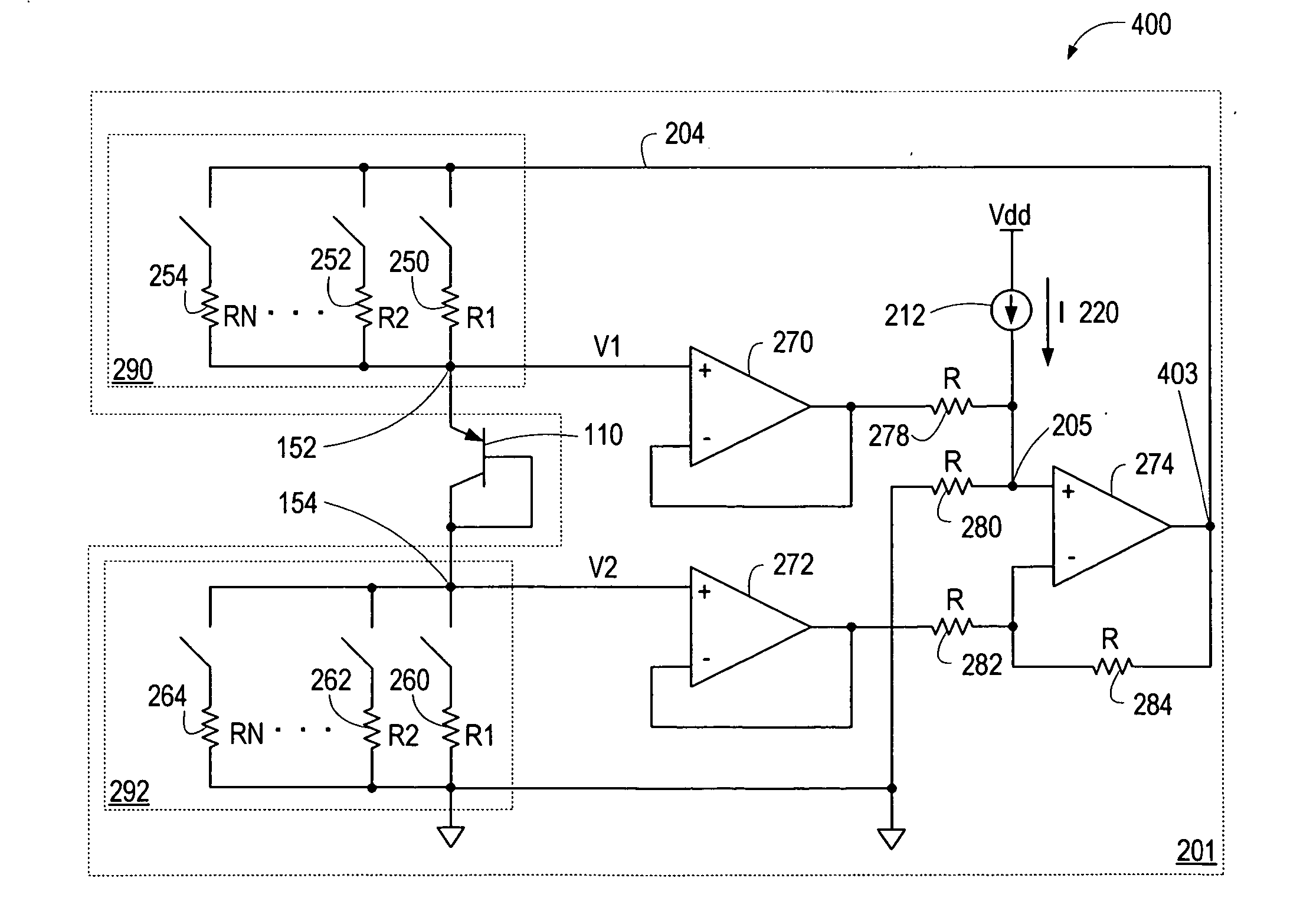
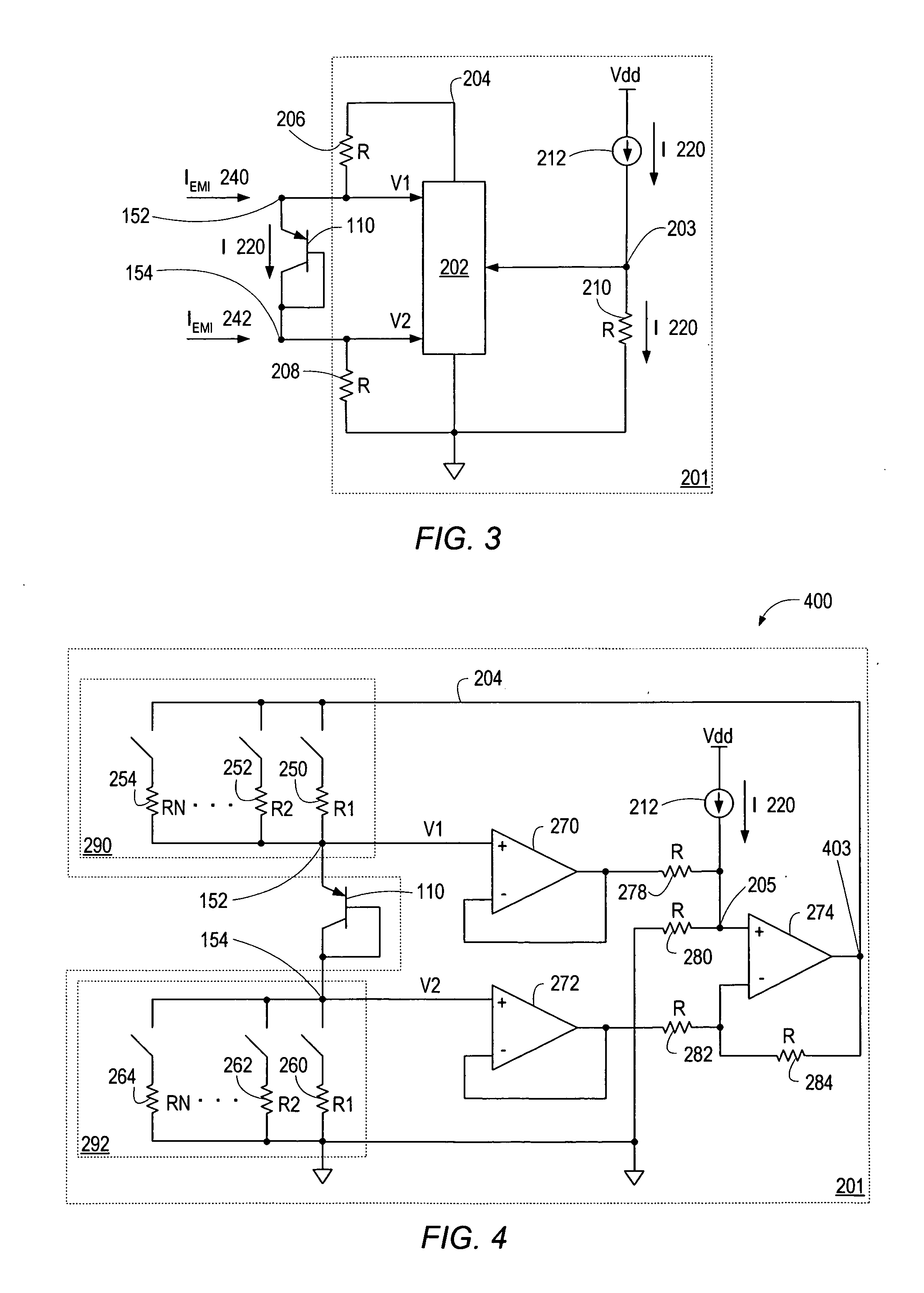
[0010] In one set of embodiments, a circuit may be implemented to deliver ratioed currents to a remotely located semiconductor device that has a substantially non-linear input-output characteristic that varies with temperature and is subject to effects of electromagnetic interference (EMI). The circuit may be configured to use common mode rejection to reject EMI signals when performing temperature measurements using the remotely located semiconductor device, obviating the need for shunting capacitor(s) coupled across the terminals of the remotely located semiconductor device. The absence of the shunting capacitor may facilitate maintaining fast sampling rates when performing temperature measurements. The use of common mode rejection may therefore provide a more effective method for handling EMI induced currents that may lead to temperature measurement errors.
[0011] In one set of embodiments, a temperature measurement system may include a current delivery circuit configured to deliver ratioed currents to a remotely located semiconductor device, which may be a diode-connected bipolar junction transistor (BJT), used for performing the temperature measurements. The current delivery circuit may comprise two identical resistances and a control circuit having two input terminals and a control terminal, with one of the resistances coupled between the anode of the diode-connected BJT and the control terminal of the control circuit, and the other resistance coupled between the cathode of the diode-connected BJT and ground. The identical resistances may facilitate establishing identical impedances seen at both the anode and the cathode, thereby insuring that currents induced by EMI do not affect the voltage developed across the anode and the cathode.
[0012] In one embodiment, the control circuit generates and maintains a constant voltage component (or offset voltage) at the control terminal, thus developing a current (diode current) in the diode-connected BJT, and consequently a base-emitter voltage (VBE) across the anode and the cathode of the diode-connected BJT. Through superposition of voltages, the control circuit may maintain a control voltage at the control terminal, where the control voltage is equivalent to a sum of the offset voltage and the VBE developed across the anode and the cathode of the diode-connected BJT. By keeping the control voltage equivalent to the sum of the offset voltage and the VBE (developed across the anode and the cathode of the diode-connected BJT), the control circuit may insure that the offset voltage and the two identical resistances determine the value of the diode current.
[0014] In one set of embodiments, each of the two resistances may be configured as a resistor network consisting of parallel-coupled resistors, where each resistor may be individually switched in and out of its respective resistor network, thereby providing a means for varying the resistance of the respective resistor network. The current delivery circuit may include a control resistor coupled between the control terminal of the control circuit and ground, and a current source configured to deliver a constant current to the control resistor, thereby generating and maintaining the offset voltage at the control terminal. In these embodiments, varying the two resistances, while insuring that the two resistances remain identical, may vary the value of the diode current, thereby producing the required ΔVBE values for generating a digital temperature reading. The identical resistances may again operate to reduce and / or eliminate effects of EMI on VBE.

Problems solved by technology

Many digital systems, especially those that include high-performance, high-speed circuits, are prone to operational variances due to temperature effects.
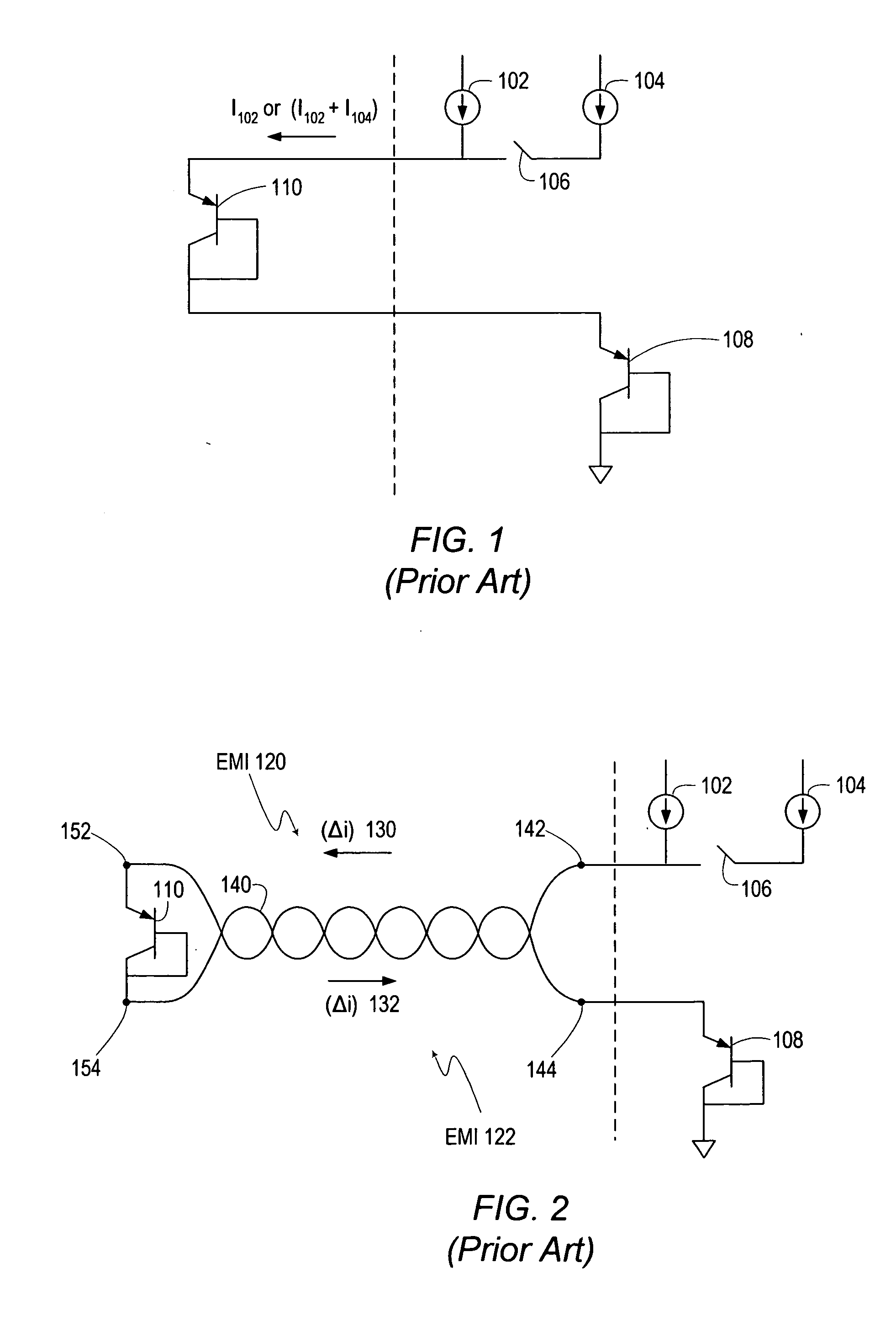
One prevalent problem with this method of delivering current to the remote diode or PN-junction when performing temperature measurements is the effects of electromagnetic interference (EMI), more specifically, currents that may be induced by EMI in twisted pair wires 140.
Slower sampling frequencies in turn lead to longer conversion times and increased power consumption of the measuring devices.
In addition, a shunting capacitor typically provides a finite amount of filtering, which may not be sufficient to enable completely accurate measurements.

Method used


Image

  • EMI rejection for temperature sensing diodes
  • EMI rejection for temperature sensing diodes
  • EMI rejection for temperature sensing diodes

Examples


Embodiment Construction

[0022] As used herein, the word “alternately” is meant to imply passing back and forth from one state, action, or place to another state, action, or place, respectively. For example, “alternately applying a first current source and a second current source” would mean applying the first current source, then applying the second current source, then applying the first current source, then applying the second current source, and so on. Similarly, “alternately setting to a first value and a second value” would mean setting to the first value, then setting to the second value, then setting to the first value, and so on.

[0023] A “diode-junction-voltage” (VBE) refers to a voltage measured across the junction of a diode, or a difference in voltage between a voltage measured at the anode of the diode junction with respect to a common ground and a voltage measured at the cathode of the diode junction with respect to the common ground. A “change in diode-junction-voltage” (ΔVBE) refers to a ch...


PUM

PropertyMeasurementUnit
constant voltageaaaaaaaaaa
resistanceaaaaaaaaaa
temperatureaaaaaaaaaa

Abstract

In one set of embodiments, a circuit may be implemented to deliver accurately ratioed currents to a remotely located semiconductor device that has a substantially non-linear input-output characteristic that varies with temperature and is subject to effects of electromagnetic interference (EMI). The circuit may be configured to use common mode rejection by establishing an identical impedance at each of the two terminals of the remotely located semiconductor device, in lieu of coupling shunting capacitor(s) across the terminals, in order to reject EMI signals while performing temperature measurements using the remotely located semiconductor device. This may facilitate maintaining fast sampling times when performing temperature measurements, while providing a more effective method for handling EMI induced currents that may lead to temperature measurement errors, thereby eliminating those errors.

Description

BACKGROUND OF THE INVENTION [0001] 1. Field of the Invention [0002] This invention relates generally to the field of integrated circuit design and, more particularly, to the design of temperature measurement circuits. [0003] 2. Description of the Related Art [0004] Many digital systems, especially those that include high-performance, high-speed circuits, are prone to operational variances due to temperature effects. Devices that monitor temperature and voltage are often included as part of such systems in order to maintain the integrity of the system components. Personal computers (PC), signal processors and high-speed graphics adapters, among others, typically benefit from such temperature monitoring circuits. For example, a central processor unit (CPU) that typically “runs hot” as its operating temperature reaches high levels may require a temperature sensor in the PC to insure that it doesn't malfunction or break due to thermal problems. [0005] Often, integrated circuit (IC) solu...

Claims


Application Information

Patent Timeline
Patent Type & Authority Applications(United States)
IPC IPC(8): G01K1/00
CPCG01K1/00G01K7/01G01K1/024
Inventor MCLEOD, SCOTT C.
Owner MICROCHIP TECH INC
Learn More