
Drift compensation for an impedimetric exhaust gas sensor by variable bias voltage

Inactive Publication Date: 2007-03-15
DAIMLER AG
View PDF7 Cites 16 Cited by
  • Summary
  • Abstract
  • Description
  • Claims
  • Application Information

AI Technical Summary

Benefits of technology

[0003] The object of the invention is therefore to provide an exhaust gas sensor for detecting a gas component in the exhaust gas of an internal combustion engine and an operating method for an exhaust gas sensor with which great long-term stability is achieved.
[0007] Applying a bias voltage to the terminals of the sensor unit as provided by the invention has the effect that the sensor characteristics are stabilized, or effects of the sensor loading or the aging-induced deterioration of the sensor characteristics are compensated. The bias voltage may in this case be an offset voltage applied in addition to the operating voltage or a voltage correcting the operating voltage. The bias voltage can preferably be set in dependence on the deviation of a sensor characteristic from a predetermined or predeterminable setpoint value. The measured variable is preferably adjusted by this settable bias voltage, so that incorrect measurements are avoided even after a long operating time and high sensor loading.
[0014] In a further refinement of the invention, the bias voltage has a positive polarity in relation to an operating voltage of a circuit of the exhaust gas sensor. The operation of an electrical heater or a measuring circuit integrated in the exhaust gas sensor may exert a more or less strong influence on the sensitivity of the exhaust gas sensor or the magnitude of the measured values, depending on the configuration of the exhaust gas sensor or the circuit. By positive pre-polarizing with respect to such a circuit, changed or aging-induced deteriorations of the characteristics of the exhaust gas sensor can be effectively compensated. In this case, the polarity of the bias voltage is preferably positive in relation to the highest potential of the circuit concerned.
[0017] In a refinement of the method, the level of the bias voltage is set in dependence on the zero drift of the electrical measured variable. This measure makes it possible to counteract both the drifting away of the zero-point value of the measured variable and the sensitivity drift of the exhaust gas sensor in the course of the operating time.
[0019] In a further refinement of the method, the level of the bias voltage is set at predeterminable points in time. The points in time may be based for example on the operating time. Renewed determination or renewed setting of the bias voltage at equal time intervals of the operation of the sensor, for instance every 10 to 100 hours, is advantageous.
[0020] In a further refinement of the method, the level of the bias voltage is set every nth time the exhaust gas sensor is switched on. Renewed determination or renewed setting of the bias voltage each time the exhaust gas sensor is switched on is particularly advantageous. This ensures the reliability of the exhaust gas sensor each and every time it is put into operation.

Problems solved by technology

However, the long-term stability of such a sensor is often unsatisfactory, which is disadvantageous for its use in exhaust gases of internal combustion engines.
This may result in aging of the exhaust gas sensor, which has unfavorable effects in particular on the long-term stability of the measured variable that is provided by the sensor unit.
This may be subject to change, for example caused by inward diffusion of foreign atoms, possibly resulting in influencing the measured variable during the operation of the circuit for temperature measurement that changes with operating time or sensor loading.

Method used


Image

  • Drift compensation for an impedimetric exhaust gas sensor by variable bias voltage
  • Drift compensation for an impedimetric exhaust gas sensor by variable bias voltage

Examples


Embodiment Construction

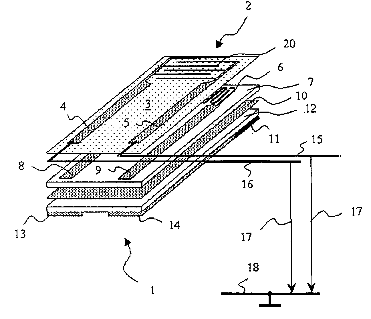
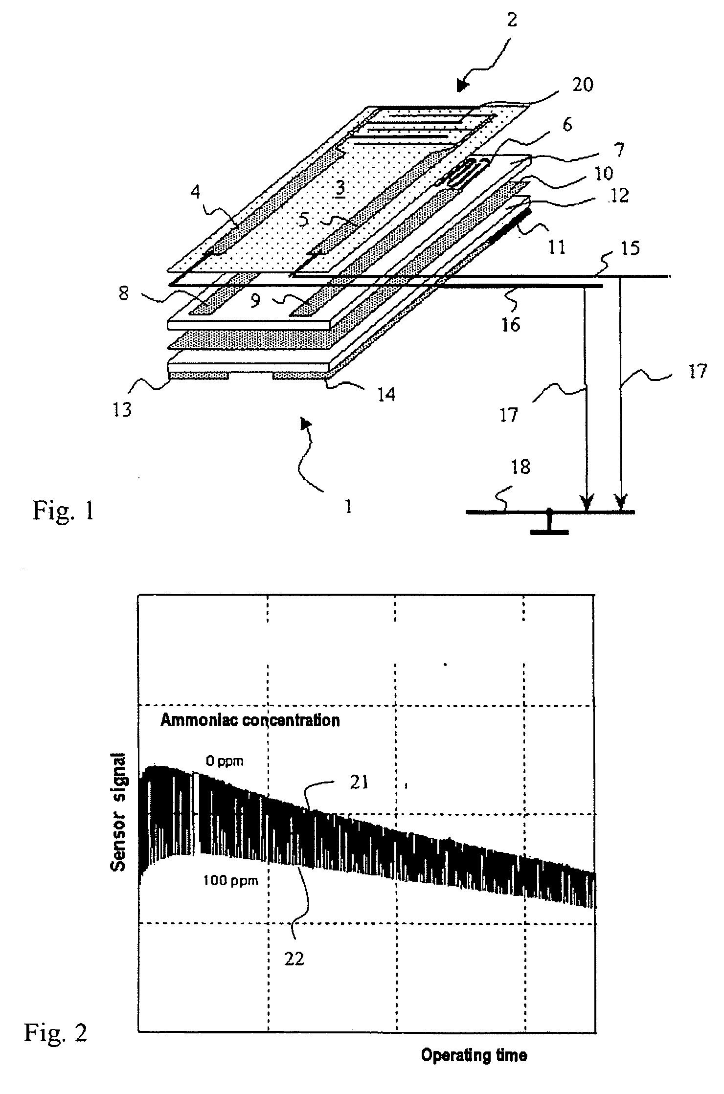
[0025] A preferred embodiment of the exhaust gas sensor according to the invention, configured by a planar technique, is explained below on the basis of FIG. 1. The exhaust gas sensor 1 is constructed on a first substrate 12, preferably formed from aluminum oxide ceramic.

[0026] Applied to the underside of the first substrate 12 is a heater structure 11 with two associated terminals 13, 14 for the connection of a heating voltage. The heater structure 11 and the terminals 13, 14 are preferably produced by a thick-film technique, alternatively also by a thin-film technique. A second substrate 7, likewise preferably formed from aluminum oxide ceramic, is arranged on the first substrate 12, it being advantageous to provide a preferably closed separating layer 10 of an electrically conductive material between the first substrate 12 and the second substrate 7, as shown in FIG. 1. In this case, a terminal (not represented) for applying an operating voltage to the separating layer 10 may be...


PUM


Abstract

An exhaust gas sensor is proposed for detecting a gas component in the exhaust gas of an internal combustion engine, having a control and evaluation unit and a sensor unit with an electrode structure with a first terminal and a second terminal, and a method for operating an exhaust gas sensor to determine the concentration of a gas component in the exhaust gas of an internal combustion engine is also proposed. The control and evaluation unit applies a bias voltage to the first terminal and / or the second terminal of the electrode structure, it being possible for the level of the bias voltage to be set in dependence on a characteristic of the sensor and / or in dependence on a loading of the sensor. A bias voltage is applied to the first terminal and / or to the second terminal of the electrode structure, with the level of the bias voltage being set in dependence on a characteristic of the sensor and / or in dependence on a loading of the sensor.

Description

BACKGROUND AND SUMMARY OF THE INVENTION [0001] This invention relates to a gas sensor for detecting a gas component in the exhaust gas of an internal combustion engine having a control and evaluation unit, and to a method of operating a gas sensor. [0002] European Patent EP 0 426 989 B1 discloses a gas sensor and an operating method for a gas sensor. The gas sensor has an electrode structure acting as a capacitor, with two terminals. The electrode structure is coated with a sensitive layer. This layer is sensitive to a gas component to be measured, it being possible for the capacitance that changes with the concentration of the gas component to be picked up at the terminals as a measured variable. However, the long-term stability of such a sensor is often unsatisfactory, which is disadvantageous for its use in exhaust gases of internal combustion engines. [0003] The object of the invention is therefore to provide an exhaust gas sensor for detecting a gas component in the exhaust gas...

Claims


Application Information

Patent Timeline
IPC IPC(8): G01M15/10G01N27/02G01N27/12G01N33/00
CPCG01N27/122G01N33/0054G01N33/0006Y02A50/20
Inventor BIRKHOFER, THOMASKNEZEVIC, ALEKSANDARMUELLER, RALFPLOG, CARSTEN
Owner DAIMLER AG
Learn More