Hearing aid

a technology of hearing aids and auxiliary devices, applied in the field of hearing aids, can solve the problems of harmonic distortion, output level must be suppressed, and user discomfort, and achieve the effect of reducing attack time and release tim

Inactive Publication Date: 2007-03-15
PANASONIC CORP
View PDF4 Cites 13 Cited by
  • Summary
  • Abstract
  • Description
  • Claims
  • Application Information

AI Technical Summary

Benefits of technology

[0014] With the arrangement as described above, it is possible to prevent that the operating point of the first transistor of the attenuation circuit is changed due to temperature.
[0015] According to the present invention, rectifying means and smoothing capacitor are used instead of RC filter wi

Problems solved by technology

For instance, when impact sound of shutting a door is inputted and if it is amplified in the same manner as low input sound, the output level gives uncomfortable feeling to the user, and the output level must be suppressed.
As

Method used


Image

  • Hearing aid
  • Hearing aid
  • Hearing aid

Examples


1st embodiment

[1st Embodiment]

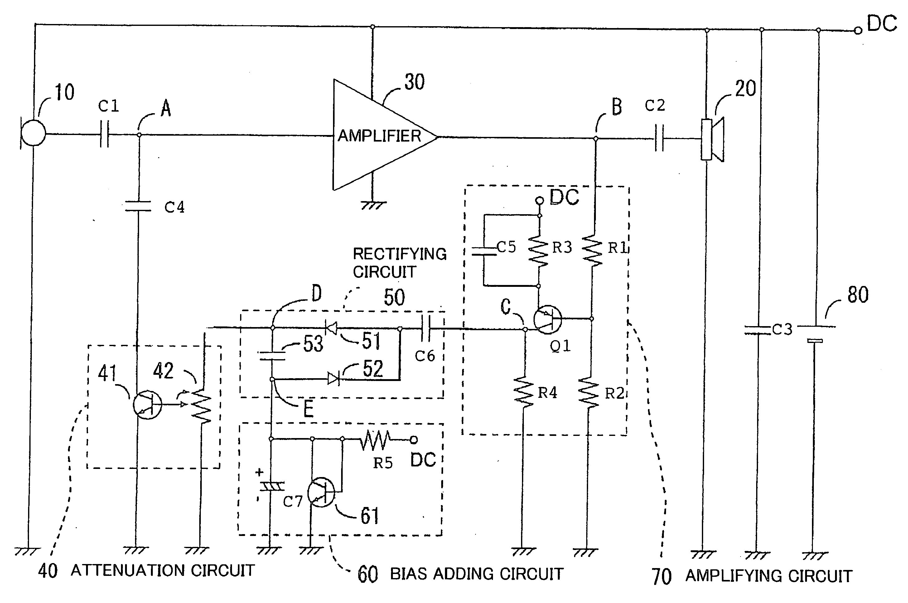
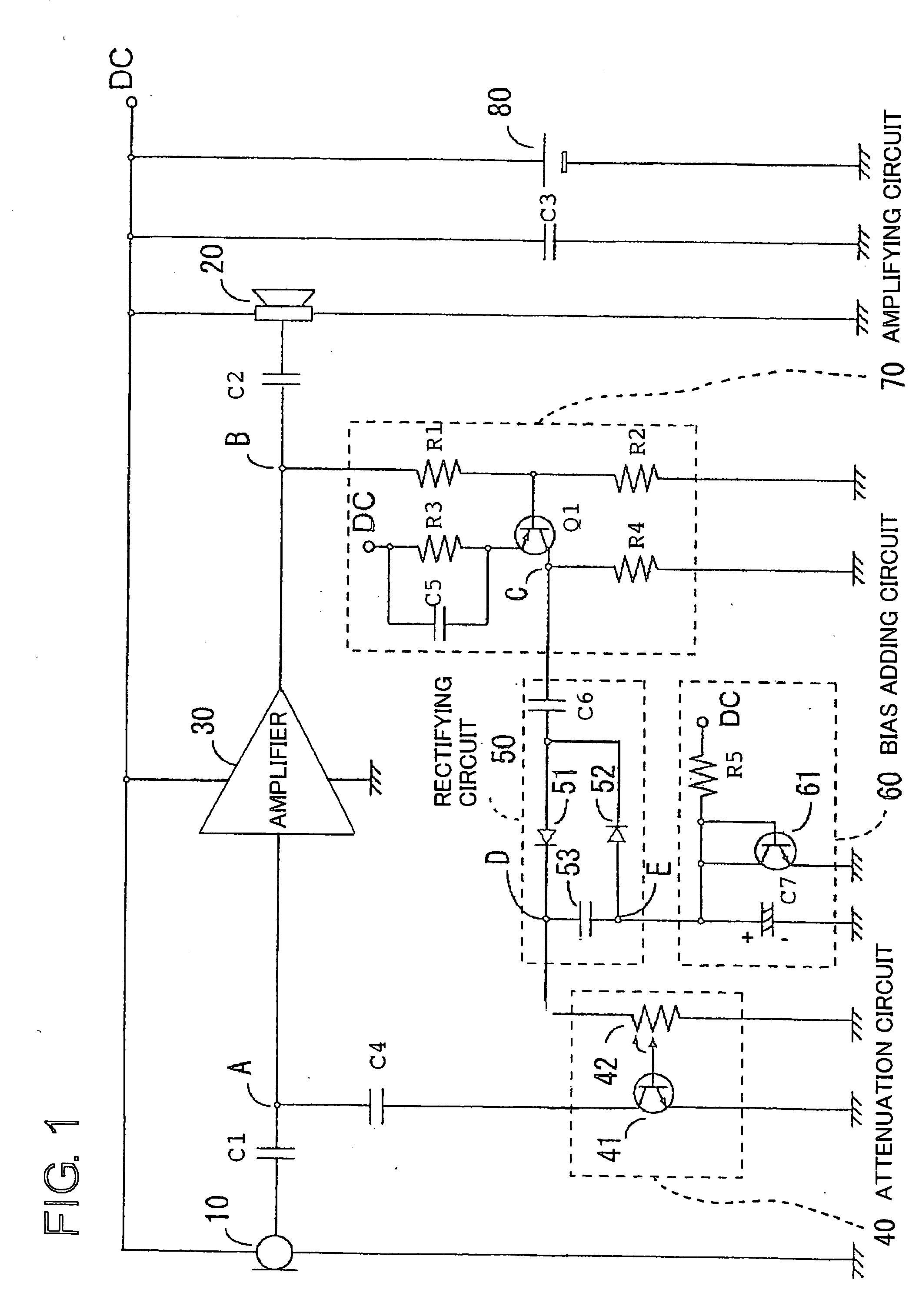
[0019] Description will be given below on embodiments of the present invention referring to the attached drawings. FIG. 1 is a circuit diagram showing an arrangement of a hearing aid in a first embodiment of the present invention. In FIG. 1, an impulse-like input signal such as excessive sound or voice or impact sound inputted through a microphone 10, i.e. an input transducer, is applied to an amplifier 30 via a capacitor C1. Then, the sound is amplified with a certain fixed gain and is outputted to an earphone 20, i.e. a receiver with a class D amplifier, via a capacitor C2. DC power is supplied to the microphone 10, the amplifier 30, and the earphone 20 via a battery 80 (and a capacitor C3). An output signal (a connection point B) of the amplifier 30 is monitored by an amplifying circuit 70 and a rectifying circuit 50, and an input signal (a connection point A) of the amplifier 30 is attenuated by a bias adding circuit 60 and an attenuation circuit 40 so that the o...

2nd embodiment

[2nd Embodiment]

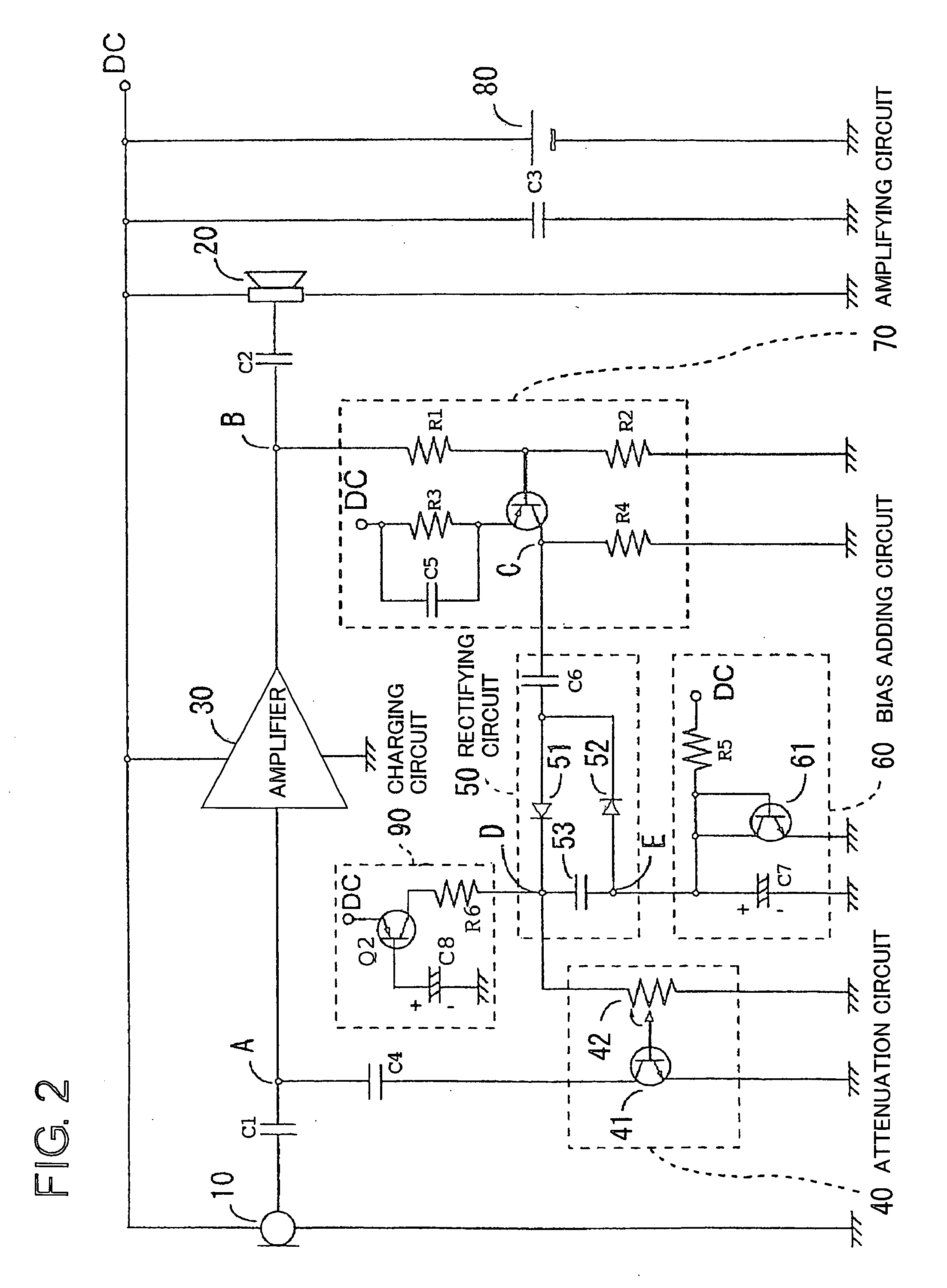
[0027]FIG. 2 is a circuit diagram showing an arrangement of a hearing aid in a second embodiment of the present invention. In the second embodiment, in contrast to the first embodiment, a charging circuit 90 (to be operated only when a power source 80 of the hearing aid is turned on) is added as shown in FIG. 2. The other arrangement is the same as that of the first embodiment, and detailed description is not given here. At the charging circuit 90, DC power is applied on the emitter of the transistor Q2. The base is grounded via the capacitor C8. Collector is connected to the connection point D, i.e. one end of the smoothing capacitor 53, via the resistance R6.

[0028] Now, description will be given on operation of the hearing aid with the arrangement as described above, referring to FIG. 2. In case of a circuit, which has no charging circuit 90, when the power 80 of the hearing aid is turned on with the automatic gain control function in operating status, pulsating c...


PUM


Abstract

A technique is disclosed, which can shorten attack time and release time without using RC filter with time constant. According to this technique, diodes 51 and 52 rectify AC signal at output stage of an amplifier 30 by voltage doubler rectification, and a smoothing capacitor 53 smoothens the signals rectified by the diodes 51 and 52. A transistor 41 of an attenuation circuit 40 turns on when DC voltage smoothened by the smoothing capacitor exceeds a predetermined level, and level of the output signal of the amplifier is attenuated by drawing the input signal of the amplifier.

Description

TECHNICAL FIELD [0001] The present invention relates to a hearing aid for automatically controlling output when impact sound or excessive sound is inputted. BACKGROUND ART [0002] Before explaining the prior art, description will be given on general features of automatic gain control in a hearing aid. In a hearing aid, it is necessary to change the gain according to the level of the input sound pressure (and not to evenly amplify the input sound). In case of a user, who is accompanied with recruitment phenomenon, it is difficult to hear low sound, while big sound or strong sound can be heard on the same level as a person with normal hearing ability. Thus, it is necessary to increase the degree of amplification when the input sound is low, and to suppress output level without amplifying very much when the input sound is high or strong and to suppress the output level to the range where the user can hear. For instance, when impact sound of shutting a door is inputted and if it is ampli...

Claims


Application Information

Patent Timeline
IPC IPC(8): H04R25/00H03G1/00H03G3/30
CPCH03G1/0082H03G3/301H04R2430/01H04R25/50H04R2225/61H04R3/007
Inventor FUJII, SHIGEKIYOKONDO, HIROSHIYOSHIZUMI, YOSHIYUKI
Owner PANASONIC CORP
Why Eureka
Try Eureka