Automated micro-well plate handling device
a technology of micro-well plates and handling devices, which is applied in liquid handling, instruments, packaged goods types, etc., can solve the problems of cumbersome devices for some handling requirements, time-consuming and laborious process,
- Summary
- Abstract
- Description
- Claims
- Application Information
AI Technical Summary
Problems solved by technology
Method used
Image

Examples
second preferred embodiment
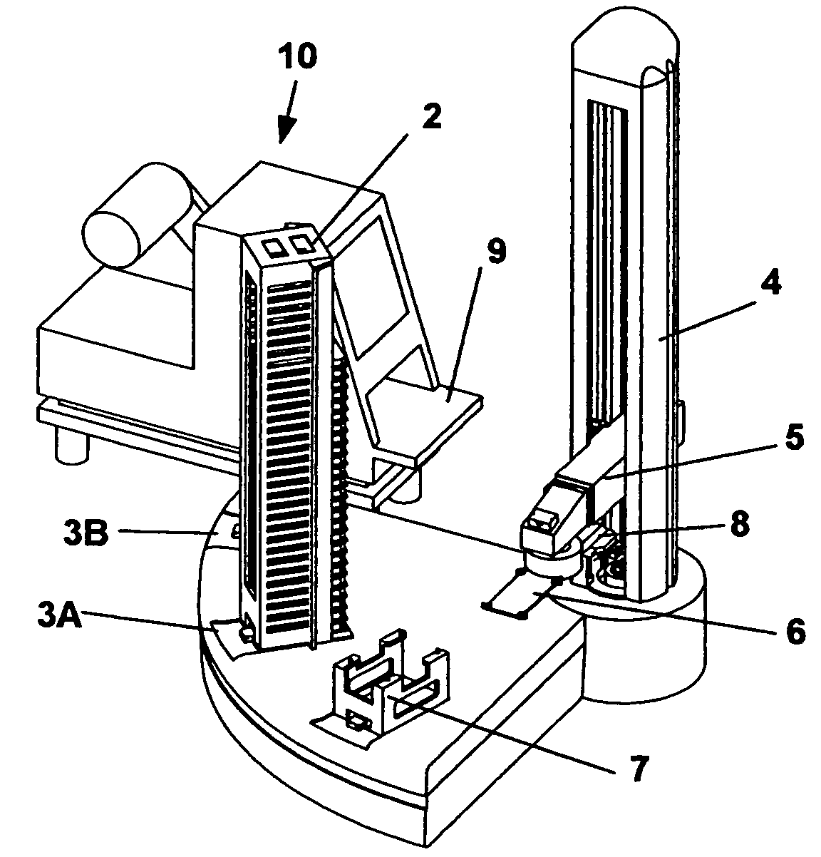
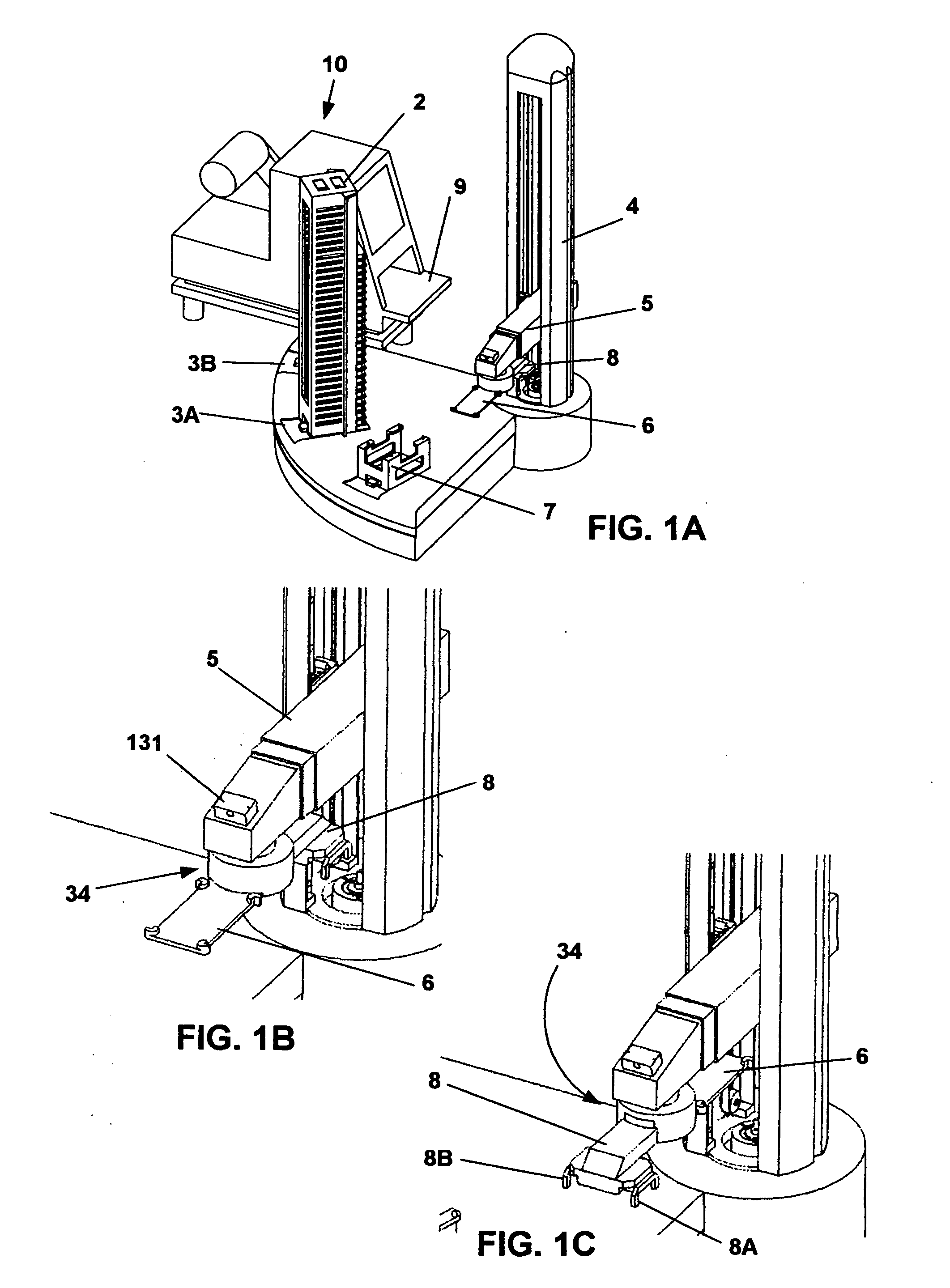
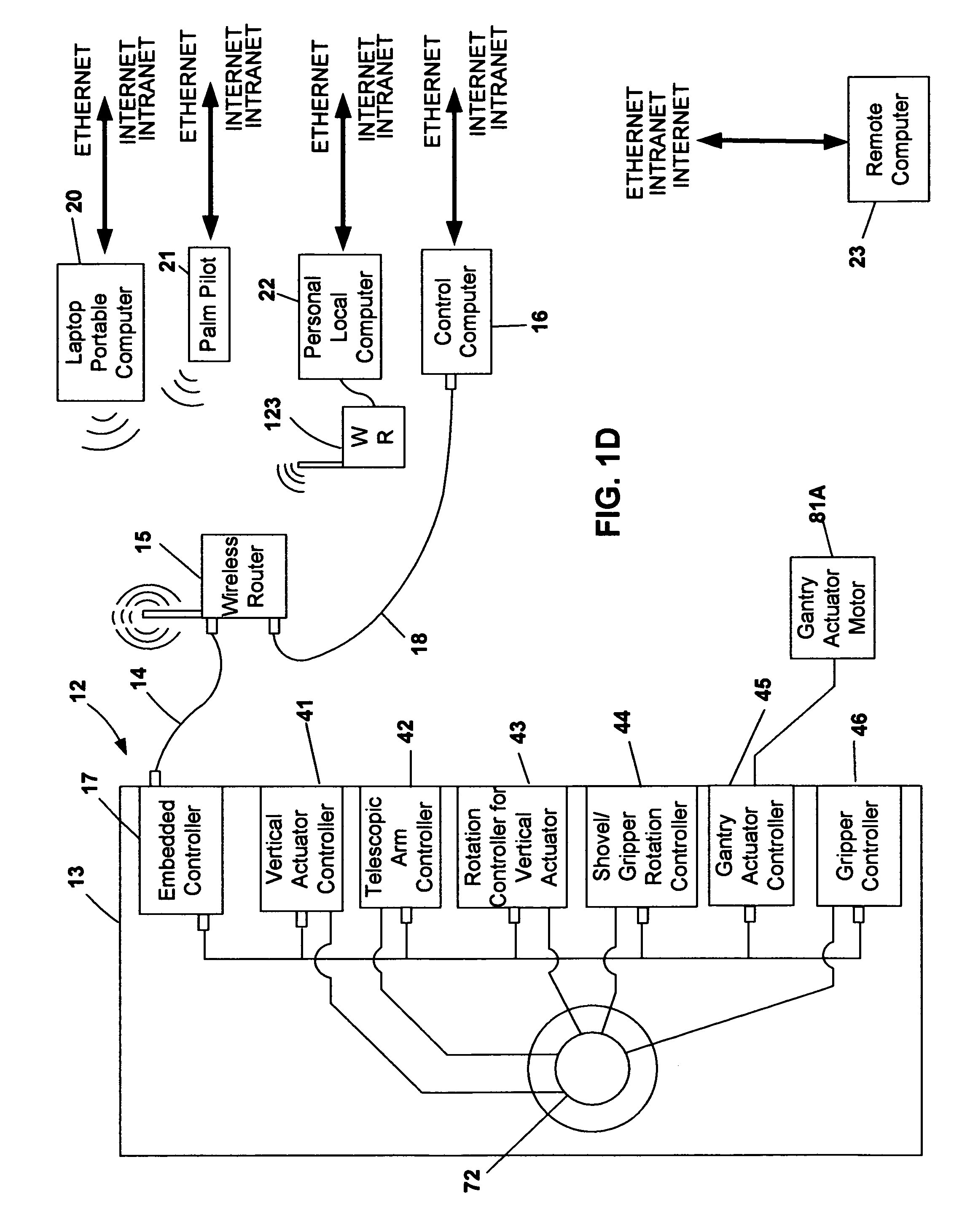
[0056] A second preferred embodiment of the present invention is shown in FIG. 24. Base 13 (FIG. 1E, 1H) with linear actuator 4 is mounted onto gantry 81. Preferably, gantry 81 is a ball screw driven linear actuator that allows for horizontal positioning of linear actuator 4. Gantry 81 is controlled by gantry motor 81A.
Utilization of the Second Preferred Embodiment
[0057] As shown in FIG. 24, a lab technician has loaded micro-well plate storage units 82A, 82B and 82C onto stations 83A, 83B, and 83C, respectively, of table 84. Receiving machines 10 and 85 have also been placed on table 84. Due to entries made by the lab technician (see above discussion), the location and orientation of micro-well plate storage units 82A-82C and receiving machines 85 and 10 are entered into embedded controller 17 (FIG. 1E). For example, as shown in FIG. 24, receiving machines 85 and 10 are both arranged so that platforms 86 and 9 have orientations that are aligned with the edge of table 84.
second embodiment
Sequence
[0058] In the following sequence shown in FIGS. 25-32, a user utilizing a portable laptop computer 20 (FIG. 1D) has logged onto the website loaded onto embedded controller 17. After reviewing the website, the user has ascertained that micro-well plate storage units 82A, 82B and 82C are positioned at stations 83A, 83B and 83C respectively. Furthermore, he has ascertained the number and locations of micro-well plates stored in each micro-well plate storage unit. Moreover, he has also ascertained the location of receiving machines 85 and 10.
[0059] After reviewing the website, the user enters instructions into embedded controller 17 for the robot to remove micro-well plate M19 from micro-well plate storage unit 82B and place it on platform 9 of receiving machine 10.
[0060] In FIG. 25, motor 81A has controlled gantry 81 so that it has moved linear actuator 4 so that telescopic gripper arm 5 is positioned in front of micro-well plate storage unit 82B. To control gantry 81, embedd...
third preferred embodiment
[0069] A third preferred embodiment of the present invention is shown in FIG. 33. The third preferred embodiment is similar to the first preferred embodiment. In the third preferred embodiment, multiple micro-well plate storage units 2 have been placed around linear actuator 4. Utilizing telescopic gripper arm 5 in a fashion similar to that described in the above preferred embodiments, in the third preferred embodiment a user can remove a micro-well plate from any of the micro-well plate storage units 2 and place the micro-well plate on transfer station 7. Because, linear actuator 4 is positioned over slip ring 72 (FIG. 1H) electrical connections can continuously be made while linear actuator 4 rotates 360 degrees or more in a clockwise or counterclockwise fashion.
PUM
| Property | Measurement | Unit |
|---|---|---|
| Area | aaaaa | aaaaa |
Abstract
Description
Claims
Application Information
 - Generate Ideas
- Intellectual Property
- Life Sciences
- Materials
- Tech Scout
- Unparalleled Data Quality
- Higher Quality Content
- 60% Fewer Hallucinations
Browse by: Latest US Patents, China's latest patents, Technical Efficacy Thesaurus, Application Domain, Technology Topic, Popular Technical Reports.
© 2025 PatSnap. All rights reserved.Legal|Privacy policy|Modern Slavery Act Transparency Statement|Sitemap|About US| Contact US: help@patsnap.com