Electrode for use in electrochemical device, solid electrolyte/electrode assembly, and production method thereof
Inactive Publication Date: 2007-03-15
HITACHI CABLE
View PDF3 Cites 104 Cited by
Summary
Abstract
Description
Claims
Application Information
AI Technical Summary
This helps you quickly interpret patents by identifying the three key elements:
Problems solved by technology
Method used
Benefits of technology
Benefits of technology
[0015] According to the invention, an electrode where an active material is in direct contact with the surface of a metal structure as a current collector can be obtained without using a conductive aid m
Problems solved by technology
However, since the electrode active material is particles independent from each other, the resistance is high and there are many particles not substantially contributing to the electrode reaction.
However, since it is difficult to uniformly contact the active material and the solidelectrolyte to each other, this increases the active material not contributing to the electrode reaction.
However, it can not be said that they are utilized effectively, for example, in that the nano size catalyst is buried in the electrolyte.
However, in a case where the active material is not physically bonded to the conductive aid material or in a case where the current flowing path from the active material to the current collector is long and, accordingly, the resistance is high, since the conduction path from the active material of the battery to the outside is restricted, it is considered that the internal resistance is high and an active material not capable of contributing to the electrode reaction is generated.
Further, an conventional electrode structure involves a problem of causing peeling between the active material and the conductive aid material due to volumic change or stress along with charge / discharge.
Therefore, the deterioration of current collection or deterioration of capacity due to powderization may increase.
Since the internal resistance of the battery increases due to the deterioration of the current collection, it also results in a problem capable of not obtaining a satisfactory battery characteristic.
As a result, the conduction path decreases and, further, the conduction path becomes incomplete upon repeating charge-discharge, and then a portion not contributing to charge / discharge may occur.
However, the conventional electrode structure has a problem that formation of interface is difficult between the active material of the electrode and the solid electrolyte membrane, as a result, active material not substantially capable of contributing to the reaction is present.
As described above, while the structure of the electrode in the electrochemical device has a great concern with the performance thereof but there exists a common subject that the active material can not yet been utilized effectively.
Method used
Image
Click on the blue label to locate the original text in one second.
Reading with bidirectional positioning of images and text.
Examples
example 1
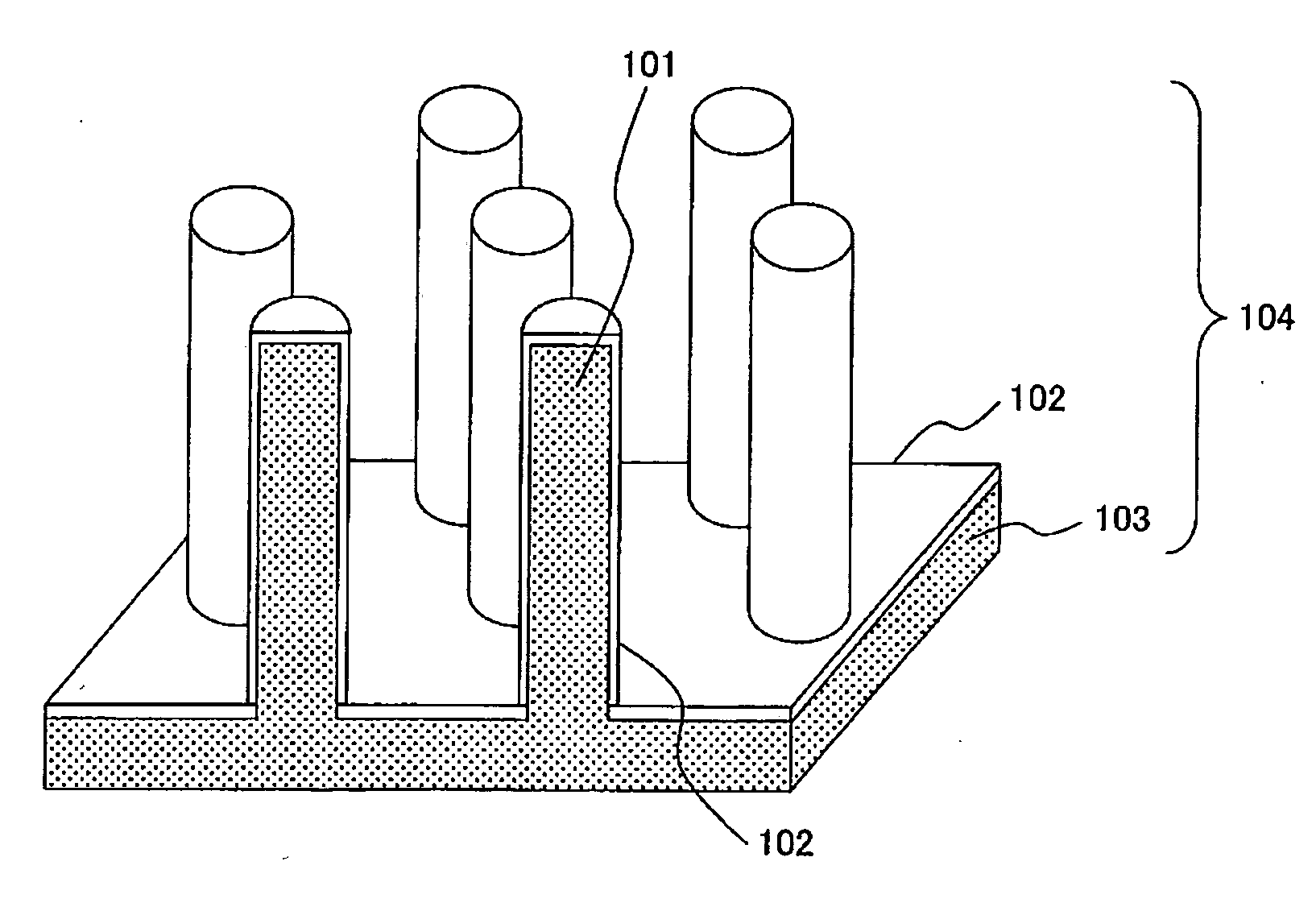
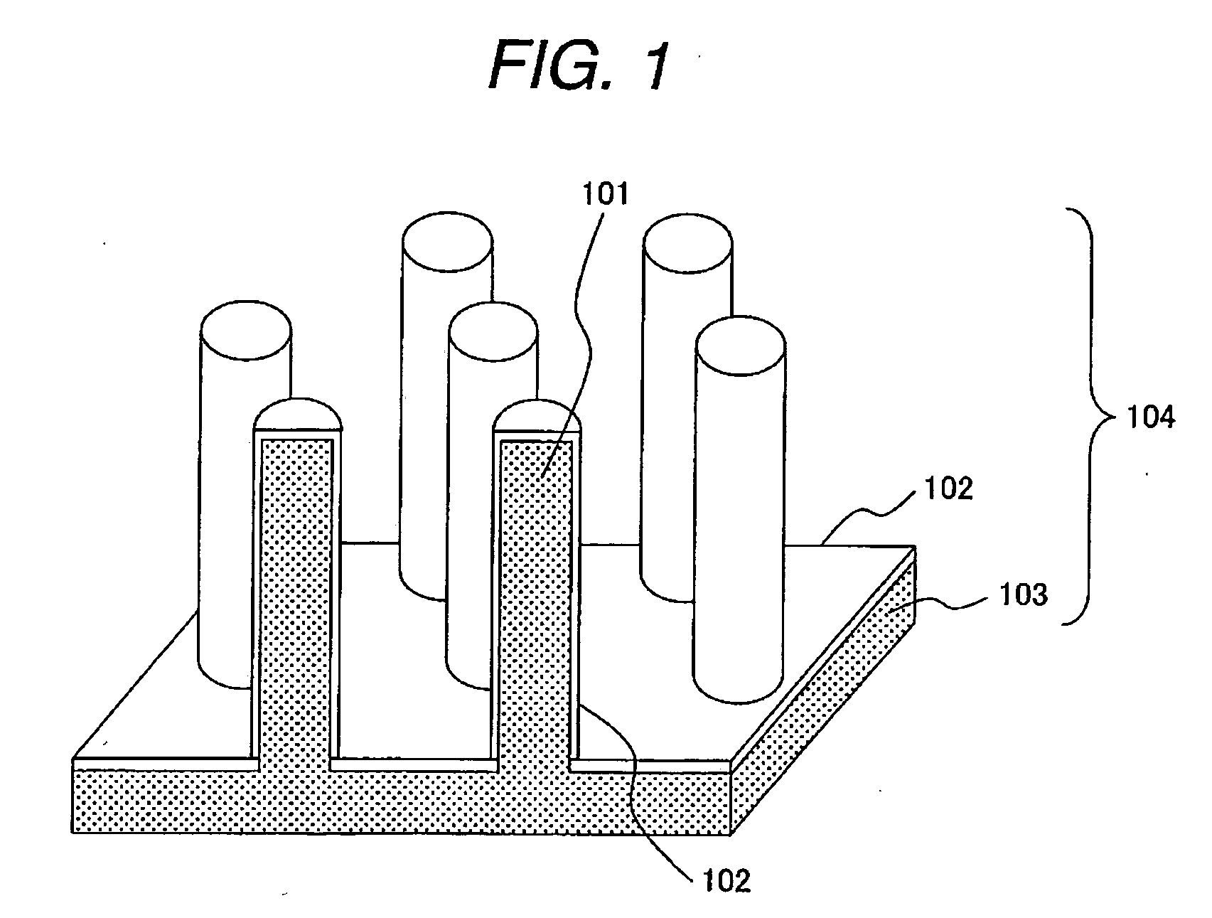
[0059]FIG. 1 is a perspective view showing an example of an electrode for use in electrochemical device according to the invention. An electrode 104 comprises a metal structure 103 having a group of micro-pillars 101 formed on the surface thereon, and an electrode active material 102. While the shape of the micro-pillar is a cylindrical columnar in FIG. 1, it may be a square cylindrical columnar (pillar) 302, and cylindrical columnar pillars and square cylindrical columnar pillars may also be present together. There is no particular restriction for the micro-pillars.
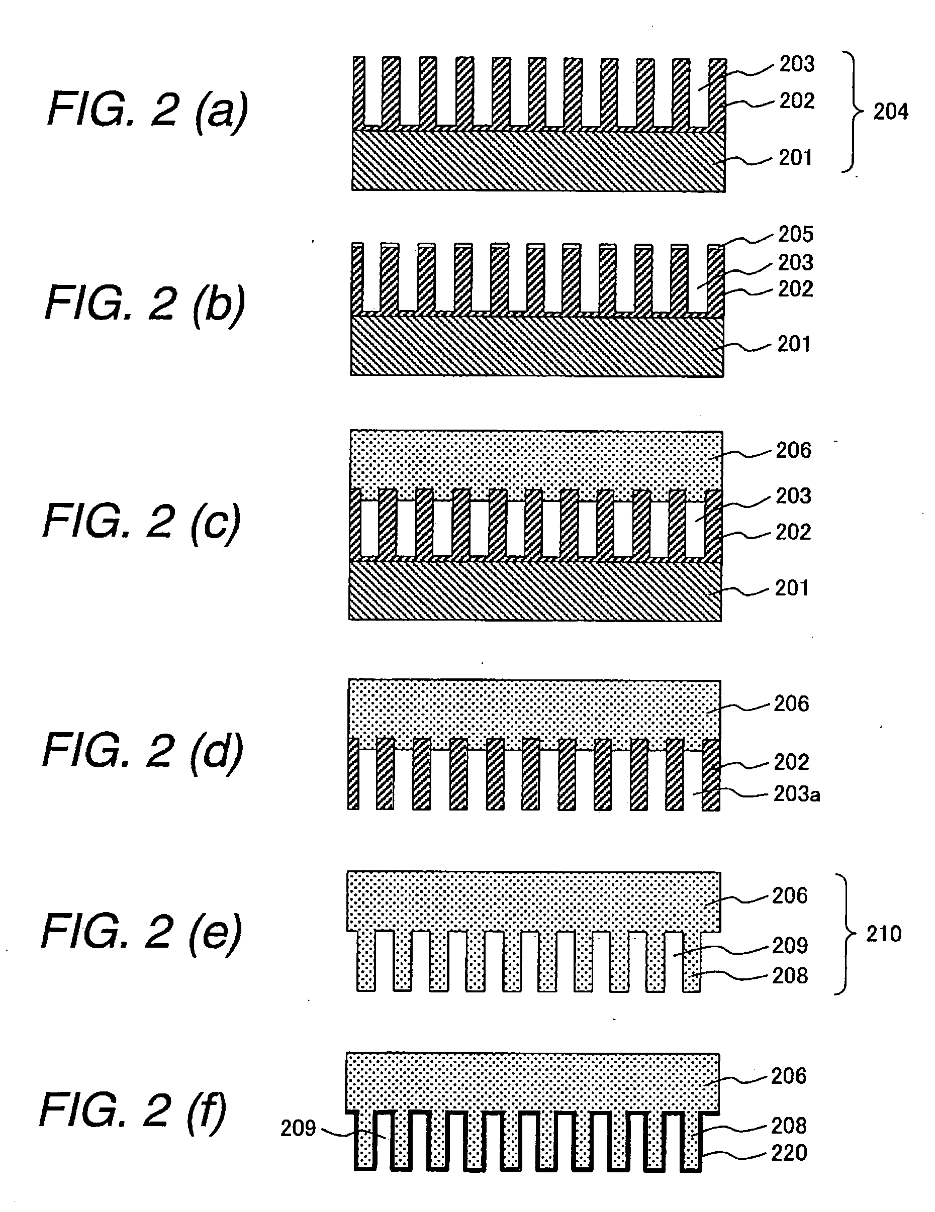
[0060] The electrode for use in electrochemical device of the shape shown in FIG. 1 was produced by production steps shown in FIGS. 2A to 2F.
[0061]FIG. 2A shows a substrate having pores. The substrate can be formed by anodic oxidation of an aluminum plate 201 in an acidic solution, for example, a solution of oxalic acid, chromic acid, or sulfonic acid. Anodized alumina 202 is formed on the surface of the aluminum plate...
example 2
[0068] In this example, a metal structure comprising nickel was produced by the same method as in Example 1, and ruthenium and platinum were formed as an active material onto the surface of micro-pillars comprising nickel. Specifically, by electrodepositing a metal structure in an aqueous alkali solution containing 0.05 mol / dm3 of rutheniumchloride, a ruthenium metal film was formed on the surface of the micro-pillar. Ruthenium was electrodeposited potentiostatically while measuring a current such that the surface thickness of nickel was about 5 nm.
[0069] Successively, platinum was deposited on the surface of the ruthenium metal film by electrodeposition using a pulse current in an aqueous solution containing 0.03 mol / dm3 of chloroplatinate. Granular platinum could be formed on the surface of the ruthenium metal film.
[0070]FIG. 5 shows a perspective view of an obtained electrode. A ruthenium metal film 502 was formed directly on the surface of each micro-pillar 208 of the metal s...
example 3
[0072] In this example, a metal structure having micro-pillars was produced by the same method as in Example 1, and a multilayered layer comprising a ruthenium metal film and a ruthenium oxide film was formed on the surface of micro-pillars comprising nickel.
[0073] Specifically, by electrodepositing the metal structure in an aqueous alkali solution containing 0.05 mol / dm3 of ruthenium chloride, a ruthenium metal film was formed on the surface. Successively, by electrochemical oxidation in a solution of sodiumhydroxide, the surface portion of the ruthenium metal film was oxidized to form a ruthenium oxide film. The solution is not restricted to that of sodiumhydroxide so long as it is an aqueous alkali solution.
[0074] Also in this example, since the active material can be formed directly to the conductive skeleton, a conducting aid for connecting the active materials to each other may not be added at all. The electrode of this example can be provided as a high performance capacit...
PUM
Property
Measurement
Unit
Structure
aaaaa
aaaaa
Abstract
In an electrode in electrochemical device, particularly an anodelithiumion secondary battery, a cathode for use in alkali storage battery, an electrode for use in fuel cell, or a capacitorelectrode, a metal structure has nano size micro-pillars is constructed with an electrode active material being formed on the surface of the metal structure. The metal structure having nano size micro-pillars can be formed, for example, by forming a metal layer as an electrode material by plating to the surface of a substrate having pores and then removing the substrate by dissolution, the metal filled in the pores of the substrate to form a group of micro-pillars. And the active material can be formed by depositing metal by plating. Since the active material is in direct contact with the conductive skeleton, the conducting agent for connecting the active materials to each other may not be added at all.
Description
CLAIM OF PRIORITY [0001] The present application claims priority from Japanese application serial No. 2005-265017 filed on Sep. 13, 2005, the content of which is hereby incorporated by reference into this application. Field of the Invention [0002] The present invention relates to an electrode for use in electrochemical device of converting, producing or depositing a material by electrochemical reaction. Further it relates to an assembly of an electrode and a solidelectrolyte. Further it also relates to a production method thereof. [0003] The present invention is suitable to be used as an electrode for use in electrochemical devices such as fuel cells, lithiumion secondary batteries, capacitors, and sensors. BACKGROUND OF THE INVENTION [0004] In recent years, along with popularization of mobile terminals such as mobile telephones or portable note type personal computers, importance of a power supply thereof receives widespread attention. It has been demanded for the power supplies ...
Claims
Application Information
Patent Timeline
Application Date:The date an application was filed.
Publication Date:The date a patent or application was officially published.
First Publication Date:The earliest publication date of a patent with the same application number.
Issue Date:Publication date of the patent grant document.
PCT Entry Date:The Entry date of PCT National Phase.
Estimated Expiry Date:The statutory expiry date of a patent right according to the Patent Law, and it is the longest term of protection that the patent right can achieve without the termination of the patent right due to other reasons(Term extension factor has been taken into account ).
Invalid Date:Actual expiry date is based on effective date or publication date of legal transaction data of invalid patent.

