Capacitor

a capacitor and hybrid technology, applied in the field of hybrid capacitors, can solve the problem that the polarizable electrode layer easily peels away from the current collector, and achieve the effects of ensuring bonding strength, preventing the peeling of the polarizable electrode layer from the current collector, and improving energy density

Inactive Publication Date: 2011-03-31
SEMICON ENERGY LAB CO LTD
View PDF21 Cites 11 Cited by
  • Summary
  • Abstract
  • Description
  • Claims
  • Application Information

AI Technical Summary

Benefits of technology

[0008]In the pressing treatment performed in the above-mentioned coating method, a polarizable electrode layer with a uniform thickness is formed to stabilize the characteristics of a capacitor. On the other hand, by increasing a density of the active material, the bonds between activated carbons is promoted to lower the resistance of the electrode; thus, the energy density of the capacitor is improved. For these reasons, the pressing treatment is one process that is extremely important for controlling the performance of the capacitor. However, if a pressure of the pressing treatment is raised too much in order to ensure uniformity of the polarizable electrode layer, or to increase a density of the active material, the bonding strength between the polarizable electrode layer and the current collector drops, and after performing the pressing treatment, the polarizable electrode layer easily peels away from the current collector.
[0009]By increasing the ratio of the binder used in the polarizable electrode layer, the bonding strength between the polarizable electrode layer and the current collector can be increased to some extent. However, the binder itself is in many cases an insulator. Accordingly, when a ratio of the binder is simply increased for increasing the bonding strength, an internal resistance of the capacitor is increased by the resistance of the electrode being increased, and the merit of the capacitor to be able to charge and discharge in a short amount of time is inhibited.
[0010]In view of the above problems, it is an object of the present invention to provide a method of manufacturing a capacitor in which a pressing treatment can ensure uniformity of a polarizable electrode layer, can apply approximately enough pressure to sufficiently raise a density of an active material, and can prevent peeling of the polarizable electrode layer from the current collector. Further, in view of the above problems, it is an object of the present invention to provide a capacitor having stable characteristics and an improved energy density while sufficiently ensuring a bonding strength between the polarizable electrode layer and the current collector.
[0016]In an embodiment of the present invention, according to the above-mentioned structure, the capacitor is formed in which uniformity of a polarizable electrode layer is ensured, approximately enough pressure can be applied so that a density of an active material can be sufficiently raised, and peeling of the polarizable electrode layer from a current collector can be prevented. Further, according to an embodiment of the present invention, while sufficiently ensuring a bonding strength between the polarizable electrode layer and the current collector, a capacitor having stable characteristics and an improved energy density can be obtained.

Problems solved by technology

However, if a pressure of the pressing treatment is raised too much in order to ensure uniformity of the polarizable electrode layer, or to increase a density of the active material, the bonding strength between the polarizable electrode layer and the current collector drops, and after performing the pressing treatment, the polarizable electrode layer easily peels away from the current collector.

Method used


Image

  • Capacitor
  • Capacitor
  • Capacitor

Examples


embodiment 1

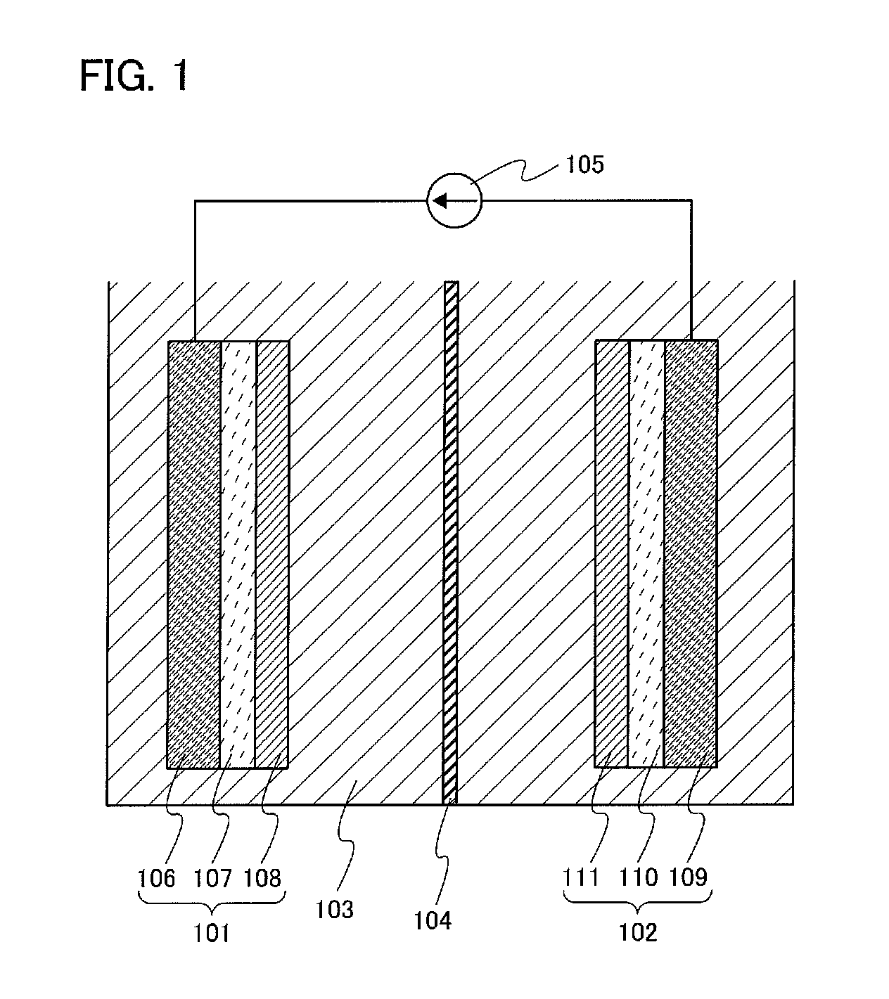
[0023]According to an embodiment of the present invention, a structure of an electric double layer capacitor with reference to FIG. 1 is described. The capacitor shown in FIG. 1 includes an electrode 101 and an electrode 102 which oppose each other with a separator 104 sandwiched therebetween in an electrolyte solution 103. The electrode 101 has a current collector 106, a buffer layer 107 in contact with the current collector 106, and a polarizable electrode layer 108 in contact with the buffer layer 107. The buffer layer 107 is provided between the current collector 106 and the polarizable electrode layer 108. In a similar manner, the electrode 102 has a current collector 109, a buffer layer 110 in contact with the current collector 109, and a polarizable electrode layer 111 in contact with the buffer layer 110. The buffer layer 110 is provided between the current collector 109 and the polarizable electrode layer 111. Also, the polarizable electrode layer 108 and the polarizable el...

embodiment 2

[0043]According to an embodiment of the present invention, a structure of a lithium ion capacitor with reference to FIG. 3 is described. The capacitor shown in FIG. 3 includes an electrode 301 and an electrode 302 which oppose each other with a separator 304 sandwiched therebetween in an electrolyte solution 303. The electrode 301 has a current collector 306, a buffer layer 307 in contact with the current collector 306, and a polarizable electrode layer 308 in contact with the buffer layer 307. The buffer layer 307 is provided between the current collector 306 and the polarizable electrode layer 308. In a similar manner, the electrode 302 has a current collector 309, a buffer layer 310 in contact with the current collector 309, and a polarizable electrode layer 311 in contact with the buffer layer 310. The buffer layer 310 is provided between the current collector 309 and the polarizable electrode layer 311. Also, the polarizable electrode layer 308 and the polarizable electrode lay...

embodiment 3

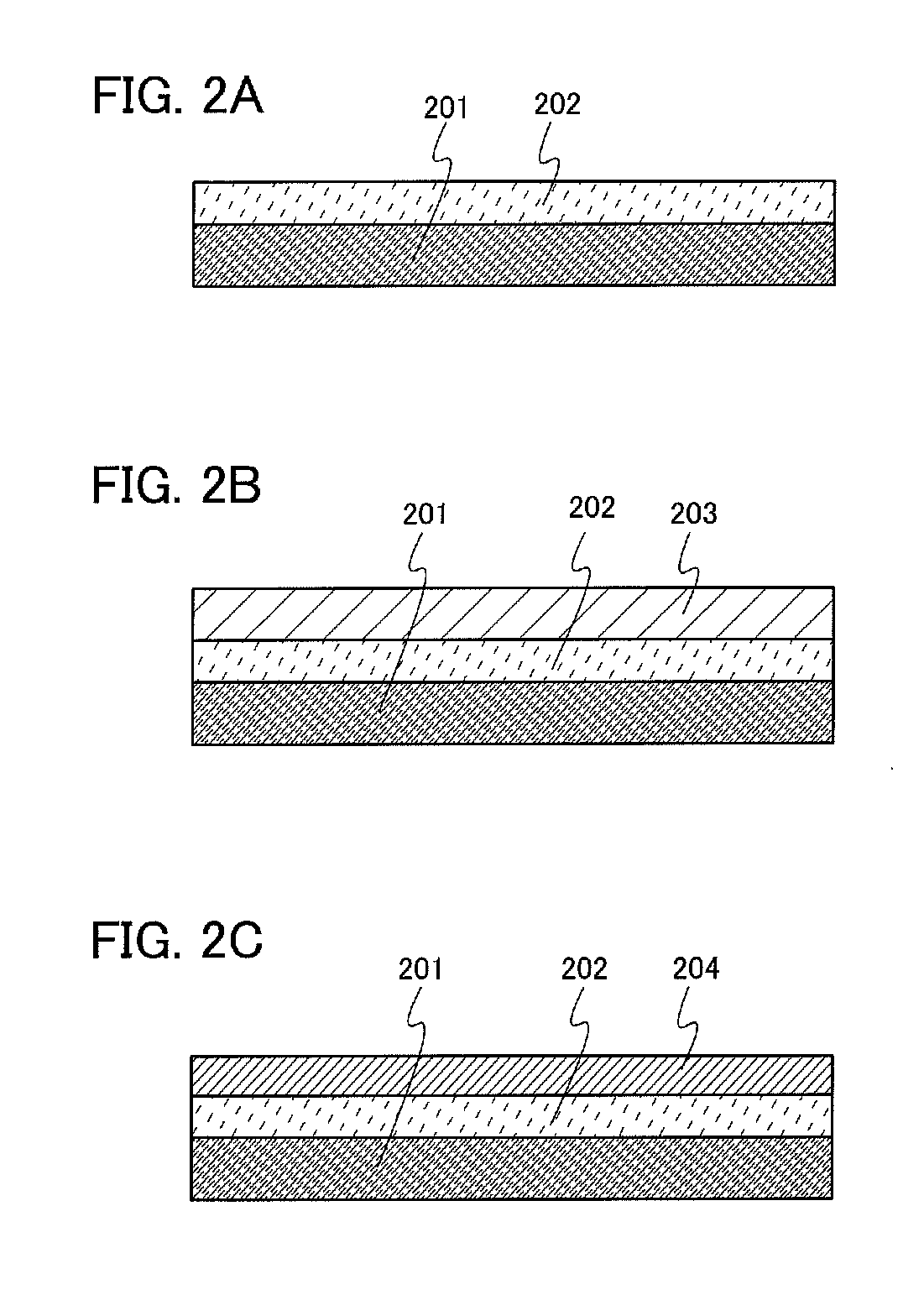
[0064]In this embodiment, a method of manufacturing an electrode included in a capacitor according to an embodiment of the present invention is described.

[0065]First, a buffer layer 202 is formed on the current collector 201 as shown in FIG. 2A.

[0066]The specific examples of the current collector 106 and the current collector 109 described in Embodiment 1 can be used for the current collector 201. In this embodiment, an aluminum foil can be used as the current collector 201.

[0067]The buffer layer 202, as described in Embodiment 1, includes a ratio of 60 wt % to 90 wt %, preferably 70 wt % to 80 wt %, of a carbon nanofiber or a carbon nanotube. Further, other than the carbon nanofiber and the carbon nanotube, the buffer layer 202 includes a resin which functions as a binder.

[0068]In this embodiment, by mixing VGCF (registered trademark) manufactured by Showa Denko K.K. which is a gas-phase method carbon fiber, with polyvinylidene fluoride (PVDF) which functions as a binder, and N-met...


PUM

PropertyMeasurementUnit
capacitanceaaaaaaaaaa
diameteraaaaaaaaaa
lengthaaaaaaaaaa

Abstract

A capacitor having stable characteristics and an improved energy density while sufficiently ensuring a bonding strength between the polarizable electrode layer and the current collector is provided. A buffer layer including a ratio of 60 wt % to 90 wt %, preferably 70 wt % to 80 wt %, of carbon nanofiber or carbon nanotube, is formed over the current collector. Then, by forming a polarizable electrode layer over the aforesaid buffer layer, a pair of electrodes are obtained in which, the buffer layer and the polarizable electrode layer are stacked in this order over the current collector. Additionally, a capacitor is formed with the above-mentioned pair of electrodes by opposing the polarizable electrode layers to each other so as to be facing one another with a separator sandwiched therebetween in an electrolyte solution.

Description

BACKGROUND OF THE INVENTION[0001]1. Field of the Invention[0002]The present invention relates to hybrid capacitors such as an electric double layer capacitor and a lithium ion capacitor.[0003]2. Description of the Related Art[0004]In such capacitors as that of an electric double layer capacitor and a lithium ion capacitor, since a dielectric can be made thin to the molecular level, and because a surface area of the electrode can be enlarged per unit area by a porous activated carbon, an extremely large capacitance of several F to several thousand F can be obtained. Further, since a charge and discharge of the above-mentioned capacitor is fast and because its power density exceeds 1 kW / kg, great electrical power can be supplied instantaneously. Additionally, since deterioration from charging and discharging is small, reliability of the capacitor is high. Also, since the internal resistance of approximately several mΩ is low, loss of charge is small, and because the capacitor does not...

Claims


Application Information

Patent Timeline
Patent Type & Authority Applications(United States)
IPC IPC(8): H01G9/145H01G11/22H01G11/06H01G11/28H01G11/30H01G11/62H01G11/66H01G11/68H01G11/70H01G11/86
CPCH01G9/016H01G9/058H01G9/155Y02E60/13H01G11/28H01G11/36H01G11/70H01G11/12H01G11/74H01G11/22
Inventor KAWAKAMI, TAKAHIROTAKAHASHI, NADINE
Owner SEMICON ENERGY LAB CO LTD
Why Eureka
Try Eureka