Polishing machine, workpiece supporting table pad, polishing method and manufacturing method of semiconductor device

a technology of polishing machine and workpiece, which is applied in the direction of grinding drive, grinding machine components, grinding tools, etc., can solve the problems of oxidation and corrosion easily occurring on the surface, and copper being more likely to be oxidized and corroded. , to achieve the effect of reducing the manufacturing yield

Active Publication Date: 2007-03-15
FUJITSU SEMICON LTD
View PDF36 Cites 13 Cited by
  • Summary
  • Abstract
  • Description
  • Claims
  • Application Information

AI Technical Summary

Benefits of technology

[0076] In this configuration, when an abnormality is detected, the head raised above the platen (holding wafer), without being held above the platen, travels to the cleaning apparatus so as to clean at least the polished surface of the wafer. After cleaning, the operator's operation is then awaited. In this configuration, since the polishing machine stops in a state that the polished surface is cleaned, the metal wiring on the polished surface corrodes to an ex

Problems solved by technology

Incidentally, copper is more likely to be oxidized and corroded.
In addition, the surface of copper which has been polished by CMP is extremely active, and oxidation and corrosion easily occurs in the surface.
However, in the case of conventional CMP machines, copper is likely to be oxidized and corroded from a time of completion of the polish until a time of the unloading (wafers are transferred out of the polishing machines).
The inventors of the present application, however, think that the above described conventional polishing machine has the following problems.
As a result, the wiring appearing on the polished surface, particularly copper wiring, corrodes and consequently, the quality of the semiconductor device to be manufactured is deteriorated.
Since the corrosion of the copper wiring proceeds rapidly in particular, unignorable corrosion occurs even during a time of raising the head 365 and consequently, the semiconductor device becomes less reliable.
The corrosion is corrosion on the surface layer of the copper wiring, and is corrosion enough to discolor the surface of the copper wiring.
At the same time, serious corrosion enough to corrode the entire copper wiring (all the layers) occurs in case of trouble.
Since it takes normally several minutes before the operator conducts the operation, the copper wiring to which slurry is adhered corrodes through all th

Method used


Image

  • Polishing machine, workpiece supporting table pad, polishing method and manufacturing method of semiconductor device
  • Polishing machine, workpiece supporting table pad, polishing method and manufacturing method of semiconductor device
  • Polishing machine, workpiece supporting table pad, polishing method and manufacturing method of semiconductor device

Examples


first embodiment

(First Embodiment)

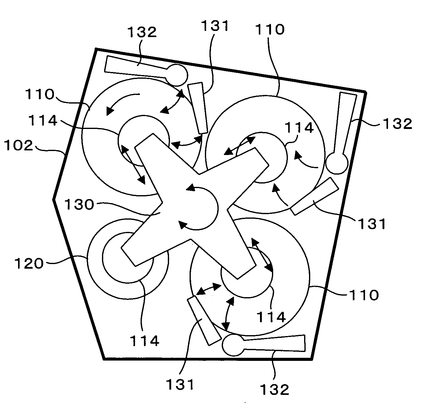
[0122]FIG. 9 is a top view showing a polishing machine (a CMP machine) according to a first embodiment of the present invention.

[0123] The polishing machine according to this embodiment is provided with three platens (polishing stages) 110 and one load cup 120 on the base 102. A slurry supplying arm 131 and a conditioning disc driving arm 132 are provided around each of the platens 110. Slurry supplying nozzles are provided to the end of the slurry supplying arm 131. A conditioning disc is attached to the conditioning disc driving arm 132. An abrasive pad (abrasive cloth) is mounted onto the top of each of the platens 110.

[0124] In addition, four polishing heads 114 are attached to a head unit 130 supported by a rotary shaft while corresponding to the platens 110 and a load cup 120. By means of causing the head unit 130 to rotate while wafers are adsorbed to, and held by, the respective polishing heads 114, the wafers are transferred to the respective platens 110...

second embodiment

(Second Embodiment)

[0157] Hereinafter, descriptions will be provided for a second embodiment of the present invention. What makes the second embodiment different from the first embodiment is that the pedestal pad arranged on the pedestal in the second embodiment is different from that in the first embodiment. The other basic configuration in the second embodiment is the same as that in the first embodiment is. For this reason, descriptions of parts and components used commonly in the first and second embodiments will be omitted here.

[0158]FIG. 21A is a plan view showing a pedestal pad 210 used in a polishing machine according to the second embodiment of the present invention. FIG. 21B is a plan view showing the vicinity of one of holes 210a in the same pedestal pad 210 in a magnified manner.

[0159] In the case of this embodiment, too, the pedestal pad 210 is formed of a sheet of polyurethane, and at least the surface of the pedestal pad 210 which comes into contact with a wafer is ...

third embodiment

(Third Embodiment)

[0163] Hereinafter, descriptions will be provided for a third embodiment of the present invention. What makes the third embodiment different from the first embodiment is that the pedestal pad arranged on the pedestal in the third embodiment is different from that in the first embodiment. The other basic configuration in the third embodiment is the same as that in the first embodiment is. For this reason, descriptions of parts and components used commonly in the first and third embodiments will be omitted here.

[0164]FIGS. 23A and 23B are plan views respectively showing pedestal pads 221 and 222 used in a polishing machine according to the third embodiment of the present invention. In the case of this embodiments, too, the pedestal pads 221 and 222 are made of a sheet of polyurethane, and the surfaces respectively of the pedestal pads 221 and 222 (the surfaces which come into contact with the respective wafers) are non-absorbable to a fluid. Specifically, the surfac...


PUM

PropertyMeasurementUnit
Metallic bondaaaaaaaaaa
Bioabsorbableaaaaaaaaaa

Abstract

A pedestal pad (workpiece supporting table pad) is arranged on the top of a pedestal (workpiece supporting table) for temporarily placing and holding a pre-polished or post-polished wafer (workpiece). This pedestal pad is formed of resin, and at least a surface of the pedestal pad which comes into contact with the wafer is non-absorbable to a fluid. The tissue of the pedestal pad is dense and smooth, and does not have any cavity, such as fine holes, which holds the fluid.

Description

CROSS-REFERENCE TO RELATED APPLICATIONS [0001] This application is based upon and claims priority of Japanese Patent Application No.2005-268274, filed on Sep. 15, 2005 and Japanese Patent Application No.2005-283802, filed on Sep. 29, 2005, the contents being incorporated herein by reference.BACKGROUND OF THE INVENTION [0002] 1. Field of the Invention [0003] The present invention relates to a polishing machine of polishing a workpiece with a slurry, a workpiece supporting table pad, and a polishing method. Specifically, the present invention relates to a polishing machine including a machine for temporarily placing and holding a pre-polished or post-polished workpiece on a workpiece supporting table; a workpiece supporting table pad; and a polishing method. [0004] The present invention also relates to a manufacturing method of a semiconductor device which is manufactured using CMP (chemical mechanical polishing) and a polishing machine suitable for CMP used for manufacturing a semico...

Claims


Application Information

Patent Timeline
IPC IPC(8): B24B7/30B24B29/00
CPCB24B37/30
Inventor SHIRASU, TETSUYAAOYAMA, KATSUHIKOAKABOSHI, FUMIHIKOGOTOH, KUNICHIROU
Owner FUJITSU SEMICON LTD
Why Eureka
Try Eureka