Lubricant with non-terminal functional groups

a technology of functional groups and lubricants, applied in the field of lubricants, can solve the problems that long chain lubricants are not easily evaporated, and achieve the effects of low free backbone length, good clearance properties, and high molecular weigh

a technology of functional groups and lubricants, applied in the field of lubricants, can solve the problems that long chain lubricants are not easily evaporated, and achieve the effects of low free backbone length, good clearance properties, and high molecular weigh

US20070060487A1Inactive Publication Date: 2007-03-15WESTERN DIGITAL TECH INC

Image

  • Lubricant with non-terminal functional groups
  • Lubricant with non-terminal functional groups
  • Lubricant with non-terminal functional groups

Examples


Embodiment Construction

[0021] The following description is of the best embodiments presently contemplated for carrying out this invention. This description is made for the purpose of illustrating the general principles of this invention and is not meant to limit the inventive concepts claimed herein.

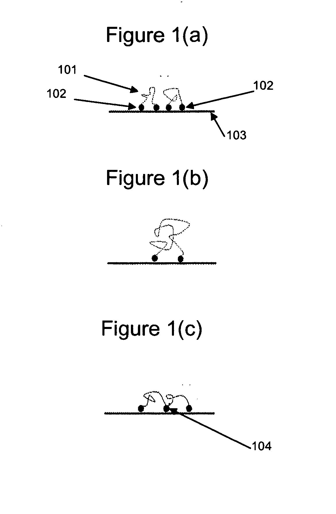
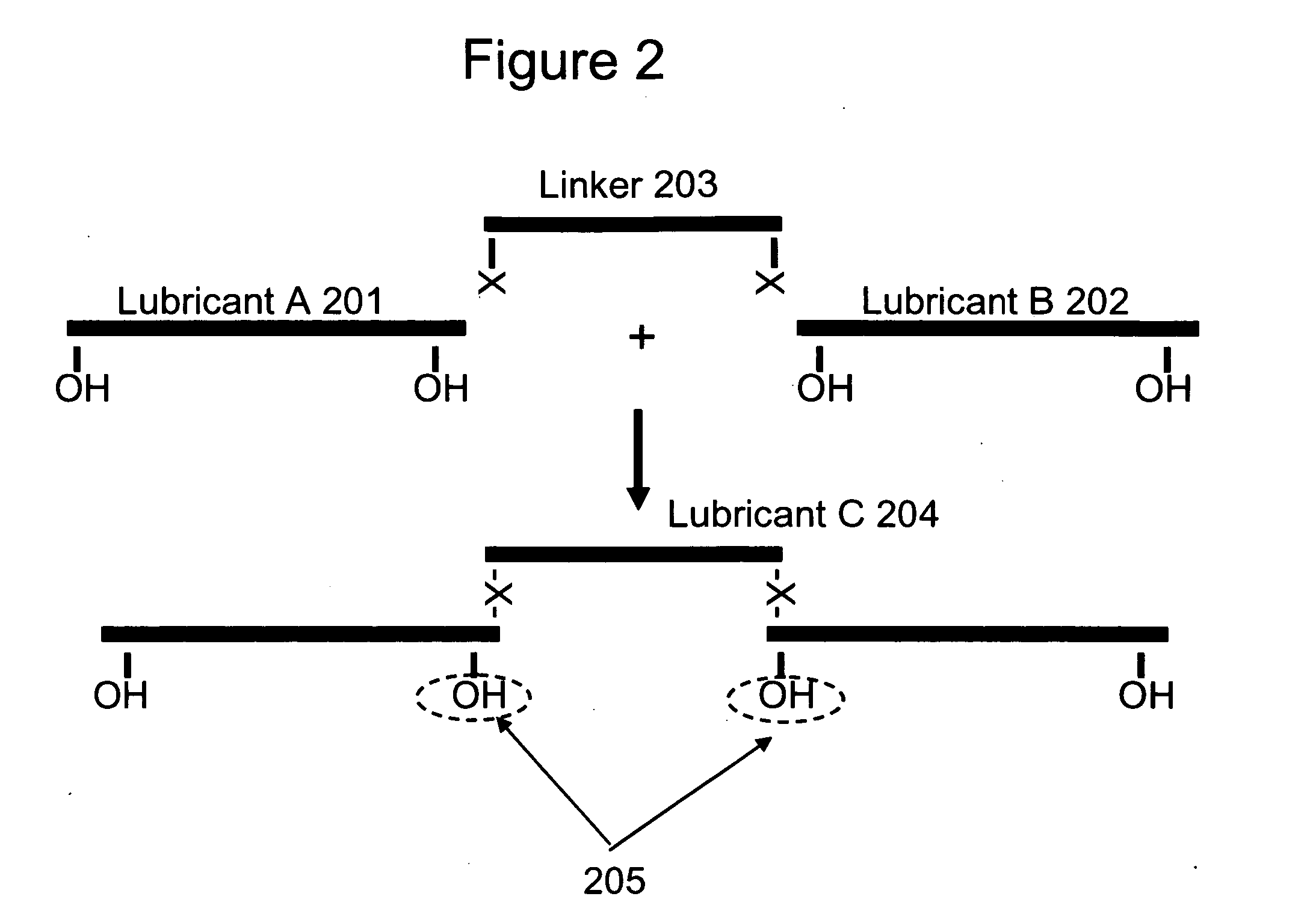
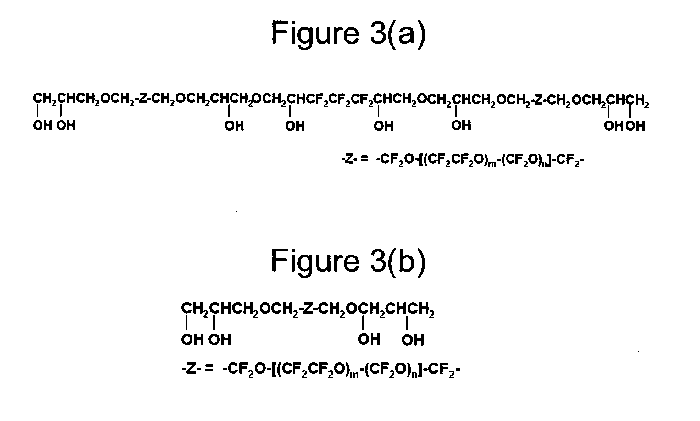
[0022] Lubricants are typically comprised of a main chain (backbone) with two attached terminal functional groups. The backbone of a lubricant is the portion of the lubricant which does not typically bind to a substrate. An example of a backbone is perfluoropolyether (PFPE). For purposes of the invention, a lubricant structure may also include two or more backbones attached at an anchor point or a plurality of anchor points. The terminal functional group attached at each end of the lubricant molecule attaches the lubricant to the surface it is lubricating. A functional group for the backbone of a lubricant provides strong interactions with a lubricated surface. Examples of functional groups are OH, piperonyl ...


PUM

PropertyMeasurementUnit
Fractionaaaaaaaaaa
Molecular weightaaaaaaaaaa

Abstract

Lubricant with non-terminal functional groups. The location of the functional groups minimizes free chain length and molecular weight of a lubricant while simultaneously maximizing evaporation temperature. The locations of the functional groups to the backbone of the molecule of the lubricant allows for shorter lengths of free backbone length between functional groups attached to a lubricated surface. The lubricant lubricates mechanical devices including hard disk drives.

Description

FIELD OF THE INVENTION [0001] The invention relates to lubricants including lubricants used to coat disks of hard disk drives. BACKGROUND [0002] Disk lubricants use linear chain molecules made of a perfluoropolyether (PFPE) backbone, with a terminal functional group attached at both ends of the backbone. These lubricants are typically known as boundary lubricants. Boundary lubricants form a lubricating film when the functional groups of the lubricant attach to a surface being lubricated. Boundary lubricants, among other advantages, prevent solid to solid contact. If the backbone in a boundary lubricant molecule is long, the molecule tends to be heavier. A longer, heavier molecule provides the advantage of less evaporation while simultaneously providing the disadvantage of increasing free backbone length. On the other hand, if the molecule's backbone is short, the molecule tends to be lighter. A shorter, lighter molecule provides the advantage of lowering free backbone length while s...

Claims


Application Information

Patent Timeline
15 Mar 2007
Publication
US20070060487A1
IPC
G11B5/00; C10M107/38
CPC
C10M107/38; C10M2213/043; C10N2220/021; C10N2220/025; Y10T428/11; C10N2240/204; G04B31/08; G11B5/725
Inventors
BURNS, JOHN MARTIN; CARTER, MALIKA D.