
Blood flow diverters for the treatment of intracranial aneurysms

a technology of intracranial aneurysms and blood flow diverters, which is applied in the field of medical devices, can solve the problems of increased aneurysm pressure, aneurysm rupture, and inability to be expected

Inactive Publication Date: 2007-03-15
GOBRAN RIAD H +2
View PDF8 Cites 71 Cited by
  • Summary
  • Abstract
  • Description
  • Claims
  • Application Information

AI Technical Summary

Benefits of technology

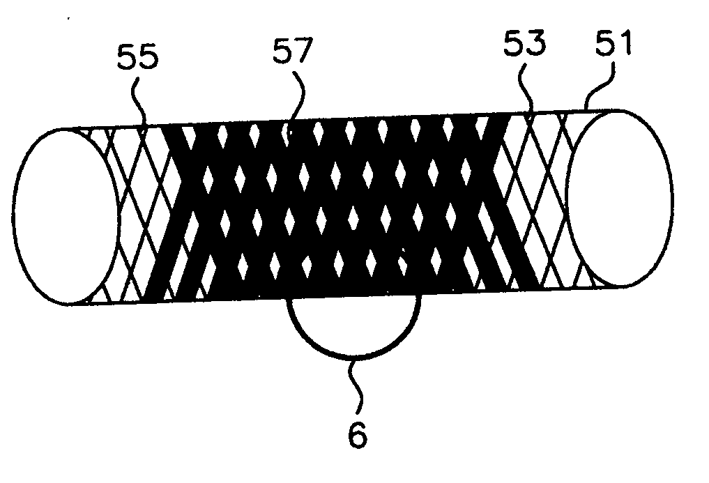
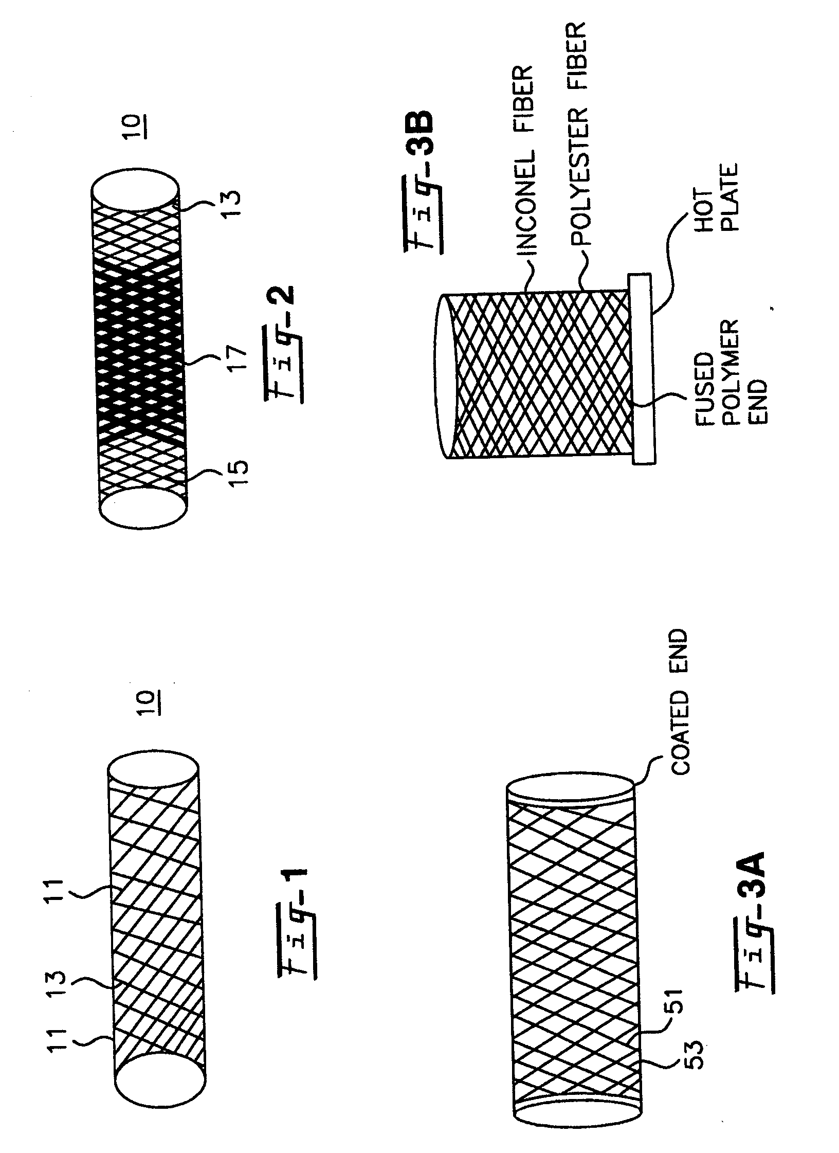
[0008] It has now been discovered that the above and other advantages of the present invention may be achieved in the following manner. The invention comprises the use of a blood flow diverter formed from a porous tubular member having a central portion and two ends. The member is of sufficient flexibility and body compatibility to be placed in proximity with an aneurysm on the outside to keep blood out of the aneurysm. The central portion has reduced porosity in two separate forms to block blood flow from entering through the aneurysm.
[0010] In one aspect of this invention, the blood flow diverter is formed from a tubular braided polymeric flow diverter using filaments of sufficiently low diameter to prevent blockage of existing perforator arteries. When the braided polymeric flow diverter is in place, it expands to decrease the porosity of the diverter and prevent damaging leakage at the aneurysm. The porosity can be decreased in the central portion by compressing the central portion or by braiding the fibers of the central portion at an angle selected to decrease that portion's porosity. An increase of the aneurysm pressure, which potentially would lead to aneurysm rupture, cannot be expected after placement of such a device in front of the aneurysm neck.
[0013] This second approach to achieve the same ultimate goal is to coat all or the middle part of the flow diverter with a reactive monomer or mixture of monomers and a suitable initiator. After the flow diverter is deployed at the aneurysm site, an ultraviolet or infrared source may be used to effect the polymerization of the monomers. The ultraviolet or infrared source can be delivered to the aneurysm site through a catheter and the source can be activated to polymerize the monomers from either the inside surface or the outside surface of the flow diverter (from the aneurysm pouch). The monomers chosen must have hydrophilic groups such that after they are polymerized, they are capable of swelling to a predetermined extent when exposed to body fluids. The swelling of the coated part of the flow diverter effectively reduces its porosity only at the region polymerized by the light source at the neck of the aneurysm.
[0014] It should be noted that the second embodiment described above may be used on any tubular device that can be placed at the location of an aneurysm. Metal devices such as those made from stainless steel, inconel, nitinol and titanium, for example, are known in the art and may be used herein with the present invention. These fibers are also used to impart radio opacity to the blood flow diverter to assist in locating the device in the patient.

Problems solved by technology

An increase of the aneurysm pressure, which potentially would lead to aneurysm rupture, cannot be expected after placement of such a device in front of the aneurysm neck.

Method used


Image

  • Blood flow diverters for the treatment of intracranial aneurysms
  • Blood flow diverters for the treatment of intracranial aneurysms
  • Blood flow diverters for the treatment of intracranial aneurysms

Examples


Embodiment Construction

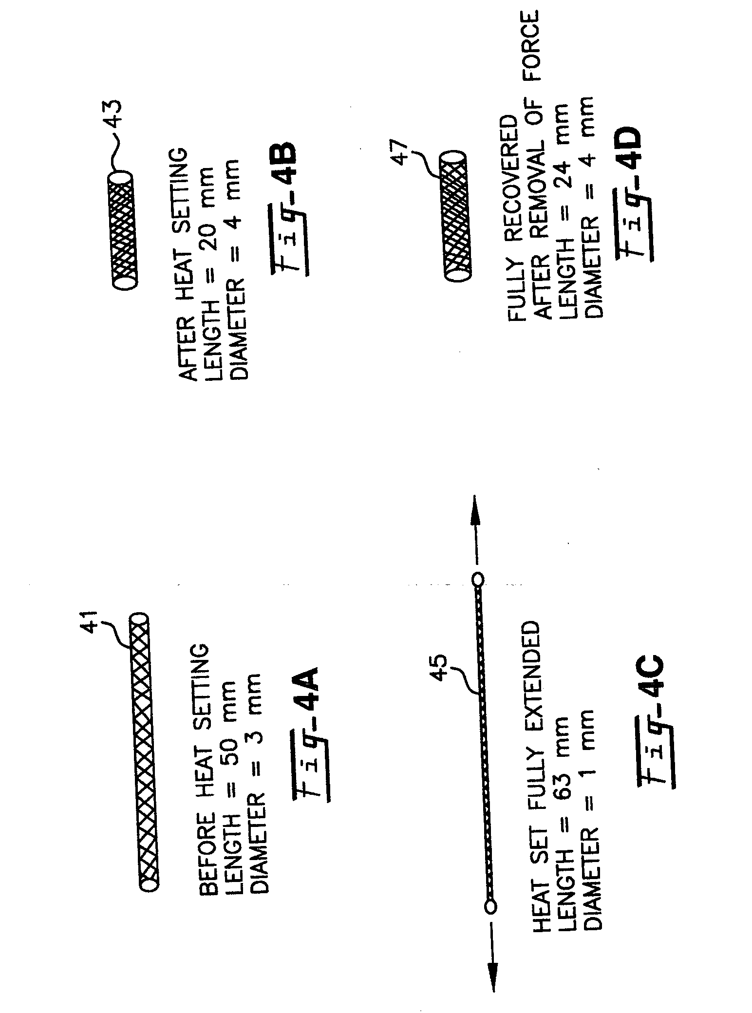
[0025] One preferred polymeric device useful as part of the present invention is produced by a sequence of steps involving the braiding of (mono- or multi-) filaments of heat-settable polymers either alone or co-braided with non heat-settable filaments of either metal or nonmetal. It is also contemplated to coat the tubular structure either partially or fully to mitigate fraying of the ends and to improve anchorage or radio opaqueness. The ends may be fused by trimming and / or heat treatment also to prevent fraying.

[0026] What is essential is that the present invention is sized to be positioned on the outside of the aneurysm rather than the prior art procedure of placing a structure inside the aneurysm. The blood flow diverter of this invention keeps blood out of the aneurysm by protecting the aneurysm from the outside. The blood flow diverter of this invention is placed over the outside of the aneurysm by a medical procedure such as by the use of a catheter and guided by a radio op...


PUM


Abstract

A blood flow diverter device for treatment of intracranial aneurysms, including a porous tubular member having a central portion and two ends. The member is of sufficient flexibility and body compatibility to be placed in proximity within an intracranial aneurysm. The central portion of the tubular member has a sufficiently decreased porosity to block blood flow from entering through the aneurysm. This is done by one of three methods: (1) the central portion of the member can be compressed to decrease porosity and heat set to hold the compression; (2) the angle of the fibers can be altered if the tubular member is made from a braided fibers; or (3) a monomeric coating can be formed on the central portion in an amount sufficient to decrease the porosity of the central portion upon polymerization of the monomeric coating. In the third embodiment a polymerization initiator is provided for polymerizing the monomeric coating upon command to cause the decreased porosity to block the blood flow. The device is heat set after compression to permit insertion and expansion in the patient. The tubular member has sufficient porosity at the two ends to keep open small perforator arteries proximate to the intracranial aneurysm.

Description

FIELD OF THE INVENTION [0001] This invention relates to medical devices. More particularly, the invention relates to flexible and elastic devices produced using, for example, heat-settable polymer filaments or biocompatible metals, that can be used as blood flow diverters for intracranial aneurysms that change their porosity once placed within the artery. BACKGROUND OF THE INVENTION [0002] A wide variety of medical devices are now available for the treatment of intracranial aneurysms. The standard surgical approach entails after craniotomy, the placement of a clip across the neck of an aneurysm to exclude it from the main circulation. The goal is to prevent a (re)bleed into the brain from an aneurysm rupture. The standard surgical approach is being replaced by minimally endovascular techniques. Most of the techniques involve the placement of platinum coils, which are after securing them within the aneurysm pouch, detach either mechanically (Cordis, Microvention) or using electricall...

Claims


Application Information

Patent Timeline
Patent Type & Authority Applications(United States)
IPC IPC(8): A61F2/06
CPCA61F2250/0023A61F2/06
Inventor GOBRAN, RIAD H.WAKHLOO, AJAY K.KHAN, YUSUF M.
Owner GOBRAN RIAD H
Learn More